VCAP5 – DCA Study Notes Resources:
The notes herein are compiled from my own testing as well as references:
- Various KB Articles
- Other References used are noted in the Section/Objective it’s used in
SECTION 1 1.1 – Implement & Manage Complex Storage
Identify RAID Levels
RAID0 = JBOD (Stripe); great performance but no redundacy
RAID1 = mirror (data copied across both disks); can lose only 1 disk; Great Read and . Write performance
RAID3 = Dedicated parity disk (min of 3 disks); can lose only 1 disk
RAID5 = Distributed Parity across all RAID disks; data loss potential during RAID rebuilds (min of 3 disks); decent Reads but Write is a division of 4 (N x Disk IOPS/4) ; N = number of disks in array
RAID6 = Dual-Parity disk distribution; N+2 redundancy during RAID rebuilds; less Read IOPS due to 2 disks lost to Parity; Poor Writes - a division of 6 (N x Disk IOPS /6)
RAID1+0 = 2 disks used for striping and mirroring (min. 4 disks); best performance & most expensive; Read = sum of all disks x Disk IOPS; Writes = . Read IOPS (N x Disk IOPS /2)
This example assumes a 6-disk RAID at 150 IOPS/disk
Two IOPS calculations
1. 1/(rotation latency + [(read latency * read %) + (write latency * write %)]) = Total IOPS Required
2. (IOPS Req’d * Read %) + (IOPS Req’d * Write % * RAID Penalty) = Total IOPS Required
Identify Support HBA Types
Types:
1. FC, iSCSI, FCoE
Vendors:
1. Broadcom, Brocade, Cisco, Emulex, QLogic
Identify Virtual Disk Format Types
Thick Lazy Zeroed (Default)
Thick Eager Zeroed – used for FT, zeroed out upon creation (Recommended)
Thin – space is allocated as written to disk
RDM – a “pointer” VMDK file that allows direct access to a SAN LUN
1. Virtual
2. Physical – not snapshot capable
Determine Use Cases for & Configure VMware DirectPath I/O (pg. 41 Networking Guide)
Uses
1. Reduce latency to a device as much as possible, as what may be needed for stock market apps needing direct access to a NIC
2. Legacy apps (or any app) may need direct access to a device (USB or NIC)
3. Can slightly improve Host performance since CPU cycles are reduced due to direct VM access to the device
Configuration (KB: http://kb.vmware.com/kb/1010789 ; pg. 145 VM Admin Guide)
1. Host BIOS – enable Intel-VTd or AMD IOMMU
2. Host > Configuration tab > Hardware box, Advanced Settings link, then Edit hyperlink for Passthrough & select the device in the list
3. VM > Edit Settings > Hardware tab, Add button; select PCI Device > Next > Finish
4. Only 6 DirectPath devices allowed per VM
Determine Requirements for & Configure NPIV (pg. 120-121 VM Admin Guide & pg. 39 Storage Guide)
NPIV – presenting many virtual ports (WWPN & WWNN assigned by vCenter) each with unique IDs using a single physical HBA
Requirements:
1. Can only be used with RDM
2. HBAs must support NPIV
3. HBAs must be homogenous vendor
4. Fabric must be NPIV-aware
5. NPIV LUN # and NPIV Target ID must match physical LUN ID/Target ID
6. *NOTE: Storage VMotion not supported
Configuration
1. Create a VM with an RDM then Edit (VM) Setting, or use current VM with an RDM
2. Options tab > Fibre Channel NPIV > Uncheck option to ‘disable NPIV’
3. Select Generate new WWNs, min of 2 WWPNs (for failover) & 1 WWNN
4. When done click OK
Determine Appropriate RAID for Various VM Workloads
Based off data capture for server workloads, you can get a baseline to determine current IOPS if the current server performance is adequate; given the IOPS generated by an app/server, you can then determine what is actually needed on the backend for your storage, because there is a Write penalty that must be taken into account depending on the RAID level used
1. For example, given the Read/Write percentages and IOPS required (based off current state analysis above), you can determine what you need to configure for the workload on your SAN.
2. Other information needed is generally how many IOPS a specific disk type (i.e. SATA, SSD) generates:
3. Example – given a 400 IOPS requirement with a 65% Read/35% Write ratio, as well as potential disk types used on the backend, you can determine the minimum disks (and/or RAID level) required to meet the needs of all VMs that will be assigned to a LUN configured on this RAID Group
a. RAID1 – (400 * .65) + (400 * .35 * 2) = 540 IOPS; so, given the disk types above & their IOPS, you would need at least 4 – 15K SAS disks, 5 – 10K SAS disks, or 9 – 7.2K SATA disks
b. RAID5 – (400 * .65) + (400 * .35 * 4) = 820 IOPS; so, given the disk types above & their IOPS, you would need at least 7 – 15K SAS disks, 9 – 10K SAS disks, or 16 – 7.2K SATA disks
c. RAID6 – (400 * .65) + (400 * .35 * 6) = 1100 IOPS; so, given the disk types above & their IOPS, you would need at least 10 – 15K SAS disks, 14 – 10K SAS disks, or 23 – 7.2K SATA disks
d. RAID10 – (400 * .65) + (400 * .35 * 2) = 540 IOPS (see “a” above)
Based on the above example, costs can really add up; though SSDs are more expensive, it may be more cost-effective to implement them as far fewer disks are needed to meet required IOPS
Apply VMware Storage Best Practices (FC, iSCSI, NFS in Storage Guide)
Fibre (pg. 57)
1. 1 VMFS per LUN
2. Don’t change MPP that’s pre-set unless implications are understood
3. Document environment
4. Plan for failure (i.e. configure redundancy)
5. Install HBAs in appropriate Host slots based on bus speed
6. Sparingly change LUN IDs as doing so renders datastores & thus VMs inactive requiring a resignature
7. Ensure RAID Groups used for vSphere have all its LUNs assigned to ESXi Host only
8. Enable Read & Write cache
9. Enable SIOC
iSCSI (pg. 105)
1. Same as noted for FC
2. Isolate storage traffic on its own VLAN
3. Have enough pNICs to support storage traffic
NFS
1. Isolate storage traffic on its own VLAN
2. Mount all same exports across Hosts
3. When increasing mounts, increase heap size
Understand Use Cases for RDM
Uses
1. MCSC (see this blog by VCDX Michael Webster & VMware KB on current MSCS support with vSphere: http://longwhiteclouds.com/2013/03/22/the-status-of-microsoft-failover-clustering-support-on-vmware-vsphere-5-1/ ; http://kb.vmware.com/kb/1004617)
2. NPIV
3. SAN Mgmt agents need ran inside a VM
4. Comparing Virtual & RDM Disks:
Configure vCenter Server Storage Filters (pg. 122-123 Storage Guide)
4 Storage Filters are Enabled by default
1. VMFS FIlter – config.vpxd.filter.vmfsFilter; filters out storage devices already used by a datatsore on any Host used by vCenter
2. RDM Filter – config.vpxd.filter.rdmFilter; filters out LUNs already referenced by an RDM on any host managed by vCenter
3. Same Host & Transports Filter – config.vpxd.filter.SameHostAndTransportsFilter; filters out LUNs ineligible for use as datastore extents because of an incompatibility
4. Host Rescan Filter – config.vpxd.filter.hostRescanFilter; auto rescans & updates datastores after performing datastore mgmt
Configure via vCenter > Home > Administration > vCenter Server Settings > Advanced Settings
1. Type in the attribute and the value to Disable the filter (type False) then click Add, then OK
Understand & Apply VMFS Re-Signaturing (pg. 120-121 Storage Guide)
When a Datastore is created it is assigned a UUID stored in the Filesystem superblock; in using SAN snapshotting or replication when presenting the LUN to vSphere, it’ll read the VMFS volume as a copy; the Datastore can either be mounted with orig UUID or change the UUID, thus “resignature”
Other operations that might cause a host to mark a Datastore as a ‘copy’:
1. LUN ID change
2. SCSI Device Type change
3. SPC-2 compliancy enablement
Mount with existing signature
1. NOTE: This can only be done for example when needing to mount the volume at a DR site and doesn’t ‘collide’ with a current/existing Datastore with the same UUID; in other words, to mount the copy, the original must be offline
2. Host > Configuration tab > Storage Adapters (Rescan storage adapters), then Storage link > Add Storage hyperlink, Disk/LUN, Next then select to Keep Existing Signature
Resignature – ESXi assigns a new UUID & label to the copied datastore & mounts it distinctly from the orig
1. NOTE: resignaturing is irreversible, is crash tolerant (i.e. can resume if process interrupted), no longer a LUN Copy
2. If Datastore is currently mounted, rt-click & select unmount
3. Rescan storage adapters
4. Host > Configuration tab > Storage Adapters (Rescan storage adapters), then Storage link > Add Storage hyperlink, Disk/LUN, Next then select to Assign a New Signature
5. May have to unregister/re-register VMs (remove VM from Inventory then re-add)
6. NOTE: If an error displays about the resignature, log out of vCenter & perform directly on the Host
7. CMD LINE (pg. 30-31 CLI Concepts & Examples Guide)
a. Find the snapshotted LUN: esxcli storage vmfs snapshot list
b. Mount the LUN w/o resignature: esxcli storage vmfs snapshot mount –l ‘replicated_LUN’
c. Mount the LUN with resignature: esxcli storage vmfs snapshot resignature –l ‘replicated_LUN’
Understand & Apply LUN Masking Using PSA-Related Commands (pg. 167-168 Storage Guide & http://kb.vmware.com/kb/1009449)
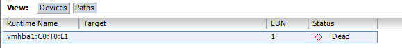
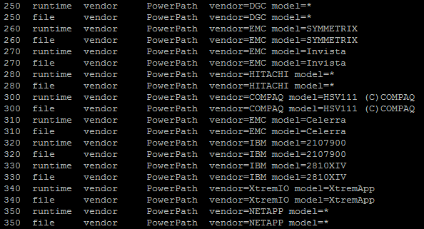
Masking – prevents Hosts from accessing certain LUNs or paths to LUNs; this is done by creating a Claim Rule that assigns the MASK_PATH plug-in to a specified path
Procedure
1. Find device name of the Datastore wanting to hide: esxcfg-mpath –L OR esxcfg-scsidevs -m
2. Check available Claim Rules: esxcli storage core claimrule list
3. Assign the plug-in to a path by creating a new Claim Rule for the plug-in (hint: may need for each path since it’s probably redundant..so for example on vmhba33 and vmhba34 but this ex only shows for 1 HBA & 1 path…will need 4 total cmds, 2 for each HBA): esxcli storage core claimrule add –r 500 –t location –A vmhba33 –C 0 –T 1 –L 1 –P MASK_PATH
4. Load Claim Rule: esxcli storage core claimrule load
5. Verify Claim Rule was added: esxcli storage core claimrule list
6. Unclaim PSA to a device: esxcli storage core claiming reclaim –d naa.UUID
7. Run the path Claim Rules: esxcli storage core claimrule run
8. Verify Mask applied: Host > Configuration tab > Storage > Refresh the view, then Rescan
a. Verify via Shell: esxcfg-scsidevs -m ; to see all Masked LUNs: esxcfg-scsidevs -c
b. Also can check if it’s active: esxcfg-mpath -L | grep naa.UUID
9. Straightline Example given on pg. 168
Analyze I/O Workloads to Determine Storage Performance Requirements
The sum of READ/s and WRITE/s = IOPS (each of these represent # of disk reads/writes per second)
Methods to monitor
1. vSphere Client – using the Performance tab
2. ESXTOP – via Shell access
3. vscsiStats – via Shell access
a. Start a capture by gathering VM ‘world ID’: vscsiStats -l
b. Run against the VM using the WID captured above: vscsiStats –w ID -s
c. Print the output & specify output type: vscsiStats –p all (or latency, seekDistance, outstandingIOs, etc.)
d. Redirect output to a file: vscsiStats –p latency > /tmp/vm01.txt
e. Stop the capture: vscsiStats –x
f. Reset vscsiStats: vscsiStats -r
Identify & Tag SSD Devices (pg. 142-146 Storage Guide)
Identification
1. ESXi5/HW8 and later
2. VMFS5 and later
3. If shared storage, device must be marked SSD on all Hosts
4. Can be easily identified in vCenter under the SSD column for Datastores
5. If the LUN isn’t yet added in vCenter, use SSH: esxcli storage core device list & view the Is SSD value
Tag (pg. 142 Storage Guide)
1. Identify device to be tagged: esxcli storage nmp device list (note the SATP of the device)
2. Add a PSA claim rule to mark device as SSD (specifying device [i.e. the ‘naa.###’ name], vendor/model, protocol, driver)
a. esxcli storage nmp satp rule add –s SATP NAME -d DEVICE NAME –o enable_SSD
b. -V vendor_name -M model_name ; --transport transport_protocol; --driver driver_name
c. Unclaim the device (by device, vendor, driver, etc.): esxcli storage core claiming unclaim -t device –d DEVICE NAME
d. Load then Run ClaimRule: esxcli storage core claimrule load then esxcli storage core claimrule run
e. Verify “tag” took: esxcli storage core device list –d DEVICE NAME and verify if Is SSD is shown as true
Administer Hardware Acceleration for VAAI
Benefits – accelerated Storage VMotion, quicker VM deployment/Cloning from Templates, assists with VMFS locking, & FT VM provisioning
Requirements
1. ESXi 4.x and greater (though not supported on NAS in 4.x)
Support in vSphere Client is when an ‘offload’ operation by Host occurs (Unkn (initial value), Suppt, Not Suppt)
Enabled by default on Block Storage
1. Pg. 173 Storage Guide shows parameters to add for disabling for each Host > Config tab > Software > Advanced Settings (and setting the value to 0)
2. Display VAAI plugin: esxcli storage core plugin list –c VAAI
3. Display VAAI filters: esxcli storage core plugin list -c Filter
4. If VAAI is listed, can display its status: esxcli storage core plugin list –N Filter
5. Display whether a device supports VAAI: esxcli storage core device get –d naa.UUID
6. Create Claim Rule for VAAI Filter: esxcli storage core claimrule add –c Filter –P VAAI_FILTER –t Vendor –V vLabs -u
7. Create Claim Rule for VAAI Plugin: esxcli storage core claimrule add –c VAAI –P VMW_VAAI_VLABS –t vendor –V vlabs –u -f
8. Load Filter: esxcli storage core claimrule load –c Filter
9. Load Plugin: esxcli storage core claimrule load –c VAAI
10. Run Claim Rules: esxcli storage core claimrule run –c Filter
Configure & Administer Profile-Based Storage (pg. 193-200 Storage Guide)
Using Storage capabilities & VM Storage Profiles to ensure VMs use storage that guarantee SLAs
Create User-Defined Storage Capabilities: Home > Management > VM Storage Profiles, Manage Storage Capabilities, Add button and give a name and description of the ‘capability’ (i.e. SSD/Tier1, SATA/Archive or Storage)
Associate these Capabilities with storage (Datastores): Datastores & Clusters > rt-click on a Datastore, ‘Assign User-Defined Storage Capability’
1. Datastores can only have 1 system-defined & 1 user-defined capability at a time
Enable VM Storage Profiles: Home > Management > VM Storage Profiles, Enable VM Storage Profiles then ‘Enable’ on a Cluster or Host(s)
Create New VM Storage Profile: Home > Management > VM Storage Profiles, Create hyperlink and enter a name for the Profile, associate the User-Defined Capability(ies), then Finish
Associate Storage Profile with VMs: rt-click VM > VM Storage Profile > Manage Profiles.. then a Profile and whether to propagate to each VMDK, OK when finished
To verify, check compliance: view on Summary tab of VM
Perpare Storage for Maintenance
To perform VMFS maintenance
1. Migrate VMs off datastore
2. Remove Datastore from Cluster (Drag/Drop out of Cluster)
3. Remove Datstore from SDRS (Done when Step 2 is done)
4. Disable SIOC
5. Remove Datastore from HA Heartbeating (if it is used)
6. Unmount the Datastore: Host > Configuration tab > Hardware box > Storage link, rt-click the desired Datastore > Unmount
a. Use esxcli if a VM is on it but pwr’d off: esxcli storage filesystem unmount –l datastore_name
7. Remount the Datastore when complete: rt-click on Datastore > Mount
Upgrade VMware Storage
Concepts
1. VMFS5 is 1MB Block Size only
2. VMFS5 sub-block is 8KB; VMFS3 is 64KB
3. VMFS3 Block Size remains when upgrading
4. VMFS5 uses GPT, but upgraded VMFS3 uses legacy MBR until data exceed 2TB then converts to GPT
5. VMFS2 needs upgraded to VMFS3 first, then to VMFS5
6. Upgrades are non-disruptive to VMs
Procedure
1. Host > Configuration tab > Hardware box > Storage link, then click on the desired Datastore & select the Upgrade to VMFS5 hyperlink
2. Or: esxcli storage vmfs upgrade -l datastore_name
1.2 – Manage Storage Capacity in vSphere
Identify Storage Provisioning Methods
Block (FC, FCoE, iSCSI, Local) & NAS (NFS)
Host > Config tab > Storage, Add
Cmd Line: vmkfstools -C vmfs5 -S datastore_name /vmfs/volumes/naa.UUID
1. NFS: esxcli storage nfs list then escxli storage nfs add –H 10.100.1.5 –s /nfs/volume_name –v datastore_name
2. Great vmkfstools examples on pg. 202-210 of the Storage Guide
Identify Available Storage Monitoring Tools, Metrics, & Alarms
Monitoring
1. Storage Views tab
a. Storage Maps
b. Storage Reports – can rt-click on columns & select what to display
c. Both update every 30mins
2. ESXTOP – storage adapter (d), device (u), & VM (v)
Metrics
1. Click an object in the Inventory > Performance tab; switch views and select different metrics
Alarms – Datastore Usage/Thin-Provisioning and VM Storage
Apply Space Utilization Data to Manage Storage Resources
Not much info here; I think if the metrics discussed previously are used, logical decisions can be made to manage the vSphere environments storage resources appropriately
Cmd Line displays: df -h OR df -h | awk ‘/VMFS*/ || /NFS/’
Provision & Manage Storage Resources According to VM Requirements
Right-sourcing was discussed in the 1st section
Can utilize Profile-Driven Storage/Storage Profiles and SDRS with Datastore Clustering to assign appropriate service levels to VMs as well as load balance Datastores
To provision a VMDK using vmkfstools: vmkfstools –c 10G –d thin –a lsilogic_sas ‘/vmfs/volumes/datastore_name/vm_name/vmdk.name
Also, storage controller of the VM can help with performance – for system disks, only buslogic/lsilogic can be used, but for data disks, if high I/O is expected, use the VMware Paravirtual controller (pvscsi)
Disk type – RDM, Lazyzeroed, Eagerzeroed, or Thin – will mostly be determined by the feature or biz requirements for the VM (i.e. FT requires ‘eagerzeroed’ disks, etc.)
Understand Interactions Between Virtual Storage Provisioning & Physical Storage Provisioning
What is provisioned as opposed what is used may be different due to concept of Thin Provisioning
1. i.e. the ‘provisioned size’ may be 20GB, but actual size only 3GB
2. Same with Datastores – ‘Capacity’ can be much smaller than ‘Provisioned’ if using Thin Provisioning
a. NOTE: VMs can be converted to ‘thick’ disks by going into its folder, rt-clicking the VMDK, & selecting ‘Inflate’ ; or by using: vmkfstools –j ‘path_to_vmdk_to_inflate’
Apply VMware Storage Best Practices
This was covered in previous section
Configure Datastore Alarms
Configure in Datastore & Clusters View
There are 5 pre-configured alarms, but a vast array of Triggers that can be used
Sort through Triggers based on Monitor type (General tab) – monitor conditions/states or events
Analyze Datastore Alarms & Errors to Determine Space Availability
This is pretty straightforward…based on Alarm thresholds, take appropriate action based on what the Alarm is alerting for
Configure Datastore Clusters (pg. 78-81 Resource Mgmt Guide)
Home > Inventory > Datastore & Datastore Clusters > rt-click on the Datacenter object and select New Datastore Cluster
Set space % utilized (default = 80%) and latency threshold (default = 15ms)
1. Advanced Options – 5% difference in storage space between source (problem) Datastore & (potential new) target Datastore, as well as how often to trigger SDRS & I/O Imbalance Threshold
1.3 – Configure & Manage Complex Multipathing & PSAs
Explain PSA Layout
See Diagram:
MPP – multi-pathing plugin supplied by partners (PowerPath V/E)
NMP – native multi-pathing plugin by VMware
1. PSP – determines path to use for I/O requests
2. SATP – determines/detects path failures
Install & Configure PSA Plug-Ins
Shell (Putty, vMA, vCLI):
1. Download 3rd Party Bundle (zip file), extract the contents, then copy to Host (i.e. in the /tmp directory) using tool like WinSCP
2. Migrate VMs off Host & place Host in Maintenance Mode
3. Install the Bundle: esxcli software vib install –d /tmp/file.xml
4. Reboot the Host
5. Check if Plug-in is registered: esxcli storage core plugin registration list
6. If not in list, register it: esxcli storage core plugin registration add –m vcap_satp_va –N SATP –P VCAP_SATP_VA
VUM
1. Download 3rd Party Bundle (zip file)
2. Home > Software & Apps > UM, Patch Repository tab then Import Patches hyperlink
3. Browse to the zip and Finish the import
4. Create a Baseline: Baselines & Groups tab > Host view > Baseline > Create
5. Name the Baseline, select Host Extension option then Next
6. Select the PSA Plug-in extension, add it (down arrow), then Finish
7. Attach the Baseline to Host/Cluster
1. Host & Clusters > UM tab, or UM > Baselines & Groups tab, then Compliance View hyperlink
2. Attach hyperlink then select the newly created Baseline then Attach
8. Stage Baseline to Host/Cluster
a. Host & Clusters > UM tab, or UM > Baselines & Groups tab, then Compliance View hyperlink
b. Select the Host or Cluster then Stage button
c. Follow wizard then Finish when done
9. Remediate Host/Cluster
a. Host & Clusters > UM tab, or UM > Baselines & Groups tab, then Compliance View hyperlink
b. Select the Host then Remediate button
c. Follow the wizard through verifying Baseline, schedule, and Maintenance Mode actions then Finish
Set new default PSP for SATP
1. List current PSAs: esxcli storage nmp satp list
2. Change default PSP: esxcli storage nmp satp set –s VMW_SATP_CX –P VMW_PSP_RR
3. Reboot Host
Change SATP for a device
4. Create Claim Rule: esxcli storage nmp satp rule add –s VMW_SATP_CX –d naa.UUID
5. List Claim Rules to be sure it was added: esxcli storage nmp satp rule list –s VMW_SATP_CX
Understand Different MPP Functionality (pg. 158 Storage Guide)
VMW_PSP_MRU – Host selects ‘most recently used’ path for I/O. When path becomes available after failure, the Host does not revert back; default for active/passive arrays
VMW_PSP_FIXED – Host selects a designated path if configured or 1st working path discovered at boot time. When path fails, Host reverts to alternate path, but when it becomes re-available, I/O is reverted back to orig/preferred path
VMW_PSP_RR – Host uses a path selection algorithm rotating through all actives paths in an A/P array, or all paths in an A/A array
Perform Command Line Configuration of Multipathing Options (pg. 47-48 CLI Concepts & Examples)
List details of a given device: esxcli storage nmp device list –d naa.UUID
Change PSP for a device: esxcli storage nmp device set –d naa.UUID –P VMW_PSP_FIXED
List Claim Rules: esxcli storage core claimrule list
1. Matches column – Claim Rule is defined for those devices (i.e. SATA, IDE, Block, etc.)
2. Rule Class column – Claim category (MP, VAAI, Filter)
3. Class column – show Rules that are defined (File parameter) and loaded (Runtime parameter)
a. User-defined Rules should have both ‘File’ and ‘Runtime’ while system-defined will only have Runtime
Display PSA Plugins on Host: esxcli storage core plugin list
Display SATPs on Host: esxcli storage nmp satp list
Set a preferred path on a device: esxcli storage nmp psp fixed deviceconfig set –d naa.UUID –p vmhba32:C:0T:1:L1
1. Verify the change took: esxcli storage nmp psp fixed deviceconfig get –d naa.UUID
Customize RR plugin: esxcli storage nmp psp roundrobin deviceconfig set –d naa.ID –I 2500 –t iops
1. Change back to default: esxcli storage nmp psp roundrobin deviceconfig set –d naa.UUID –t default
2. NOTE: items that can be changed are → -B for bytes, -I for IOPS, -U to allow RR to use an active non-optimal path
@joshcoen has a nice video at valcolabs.com/vcap5-dca on Obj 1.3 going over cmd line MPP options
Change a MPP
GUI
1. Configuration tab > Storage link, select the desired Datastore then Properties hyperlink
2. In the Datastore Properties window, select the Manage Paths button then select the appropriate Path Selection from the drop-down THEN CLICK THE CHANGE BUTTON or the change doesn’t save
Configure Software iSCSI Port Binding (pg. 78 Storage Guide; Eric Sloof video: http://www.ntpro.nl/blog/archives/1790-vSphere-5-Video-iSCSI-User-Interface-support.html)
This procedure assumes VMkernel PortGroups were previously created for iSCSI use
1. NOTE: the VMkernel PortGroups created for iSCSI cannot have > 1 vmnic associated with it beit Active or Standby
Host > Configuration tab > Hardware box > Storage Adapters, select the iSCSI Software Adapter in the list then the Properties hyperlink
From the Network tab click the Add button to display the vmnics of the Host
1. If any of the vmnics do not meet the above mentioned requirement (in sub-item 1. above), vSphere will tell you and you won’t be able to add vmnics; you must correct Teaming in the vSS VMkernel PortGroups before you can add vmnics (i.e. Port Bind); to do this, you can override the vSwitch Teaming Policy
To Port Bind via SSH: esxcli iscsi networkportal add -A vmhba33 -n vmk4
SECTION 2 2.1 – Implement & Maintain Complex Virtual Networks
Identify Common Virtual Switch Configurations (pg. 157 Networking Guide for Best Practices)
Best Practices
1. Mutliple uplinks per vSS
2. Use VMXNET3 adapter for performance
3. All VMkernel adapters should have similar MTU when connected to a vDS to avoid connectivity issues
4. No Dynamic Binding in a vDS dvPortGroup
5. Place VM traffic on separate pNICs
6. Segregate VMotion traffic via VLAN segmenting a pNIC or use a separate pNIC altogether
7. Separate networks by dedicating a service to a pNIC & vSS or by using PortGroups with VLANs
8. Load Balance (Route Based on Orig IP/IP Hash for NLB)
9. Dedicated vSS for IP Storage (iSCSI, NFS)
10. Secure Mgmt traffic
Configure SMNP
Host – can only be configured via cmd-line (pg. 135 of CLI Concepts & Examples Guide)
1. Open vSphere CLI (or other cmd-line tool: PowerCLI, Putty to SSH to host)
2. Configure the Community String: vicfg-snmp –c CommunityName
3. Configure UDP Port if not using default port 161: vicfg-snmp -p Port#
4. Configure the Target SNMP Server: vicfg-snmp -t TargetSNMPserver@Port/CommunityName
5. Enable SNMP Agent: vicfg-snmp -E
6. Show Configurations to Ensure Accuracy: vicfg-snmp -show
7. Test Send Commands to SNMP Target/Server: vicfg-snmp -test
8. Full Sample of Commands Needed:
#> cd bin (if not already there)
#> vicfg-snmp –show
#> vicfg-snmp –c public
#> vicfg-snmp –p 162
#> vicfg-snmp –t 192.168.199.5@162/public
#> vicfg-snmp –E
#> vicfg-snmp –show
#> vicfg-snmp –test
*NOTE – there is a .pl extension part of the vicfg command that must be used when vCLI is run directly on Windows. Also, to prevent the use of clear text username/pwd, a session file can be used in place of the --username --password parameters. See the CLI Getting Started Guide for procedures to create a session file. The .pl is not needed if using vMA…just cd to /sbin vCenter – can only be configured via vSphere Client (pg. 135 of vCLI Cmd-Line Concepts & Ex’s PDF)
1. Log into vCenter with vSphere Client
2. Click Home > Administration > vCenter Server Settings, select SNMP from the list
3. Configure Settings (SNMP Server, Port, Community String) as Shown Below:
Determine Use Case For & Apply VMDirectPath I/O (good Communities Doc, Whitepaper & KB: http://communities.vmware.com/docs/DOC-11089, http://www.vmware.com/files/pdf/techpaper/VMW-vSphere4-directpath-host.pdf; http://kb.vmware.com/kb/1010789)
Use Cases
1. With VMDP I/O enabled, you garner a slight performance gain to the device used for direct I/O
2. Some legacy apps need direct access to a device
3. With VMDP I/O enabled, you lose some vSphere capabilities for the VM:
a. No VMotion
b. No Storage VMotion
c. No DRS
d. No Snapshot
e. No FT
f. No Suspend/Resume
g. No Device Hot-Add
Apply/Configure (can add up to 6 devices per VM):
1. Ensure the host BIOS has proper settings enabled
(Intel VT-d or AMD IOMMU enabled, as well as Intel-V or AMD-V enabled)
2. Log into vCenter with vSphere Client
3. Select appropriate host in the left pane, then Configuration tab
4. In the Hardware box, select the Advanced Settings link, then Configure Passthrough…link
5. Scroll to the device in the list then check it to enable it
6. Place the host in Maintenance Mode, then Reboot
7. Check if IOMMU is enabled by running the following cmd in vCLI: #> vicfg-module.pl --vihost host1 --username root --password VMware1! –l
8. Verify the VM using the passthrough device is at least on HW Version 7
9. Rt-click on the VM > Edit Settings > Hardware tab > Add button
10. Select PCI/PCIe Device > Next
11. Select the device from the drop-down > Finish
Migrate a vSS to vDS/Hybrid (Whitepaper: http://www.vmware.com/files/pdf/vsphere-vnetwork-ds-migration-configuration-wp.pdf)
Procedures
1. Create vDS
a. Log into vCenter
b. CTRL+SHFT+N (Home > Inventory > Networking)
c. Rt-click on the Datacenter object > New vSphere Distributed Switch
d. Select vDS version (5.x)
e. Enter a logical name & configure # of dvUplink ports
f. Add hosts “later”
g. Select to or not to create a default dvPortGroup, review information, click Finish
2. Create dvPortGroups that mirror that of the vSS, assigning VLANs as appropriate
3. Click the new vDS > Add Host
a. To retain network connectivity, select only 1 vmnic per vSwitch and/or network service (i.e. if 2 vSwitches with 2 vmnics each, select only 1 vmnic from each vSS; or, select 3 of the 4 vmnics if using all 4 in 1 vSS)
b. Assign virtual adapters (“vmk’s” or vSS PortGroups) to a destination vDS PortGroup
c. Verify “Migrate VM Networking” is unchecked then Finish
4. Add VMs to vDS
a. In Host & Clusters, select VM > Edit Settings, Network Adapter in Hardware tab and change the VM Network to the vDS VM Network
b. Another option is in Networking view, click the vDS > Migrate VM Networking, select the source (vSS) VM Network then destination (vDS) Network, choose VMs to migrate then Finish
5. Add remaining Host vmnics
a. In Networking, select the vDS then Manage Hosts link
b. Add the remaining vmnics not earlier selected (these will show as currently unchecked)
Repeat Steps 1-4 for remaining Hosts
Delete vSS as required
Modify NIC Teaming Policies in vDS that were used on the vSS as required
1. NOTE: Teaming must be done on the dvPortGroups, not vDS itself
To Migrate using HOST PROFILES
1. Create vDS
2. Create dvPGs
3. Add a Host > Migrate vmnics > Migrate Virtual Adapters
4. Migrate VM Network
5. Add any remaining vmnics if didn’t migrate all in Step 3
6. Create dvPG Teaming & Security Policies
7. Delete vSS if required
8. Create Host Profile of Referene Host
9. Attach & Apply Host Profile to other Hosts needing to migrate to vDS
10. Migrate VM Network for VMs on the remaining Hosts
Configure vSS & vDS via Command-Line (pg. 112-123 CLI Concepts & Examples)
Use esxcli network and vicfg-<vswitch, snmp, ntp, dns, vmknic> commands
Examples:
1. NOTE: Commands using esxcli assume Putty directly to a Host; if using vMA <conn options> may need to be used to target a Host
2. List interfaces (i.e. vmk’s), MAC, & MTU size: esxcli network ip interface list
3. List individual interface char’s (IP): esxcli network ip interface ipv4 get –i vmk0 (or just ‘get’)
4. Add VMkernel interface: esxcli network ip interface add –I vmk5 –p VMotion
5. List vSS(s) & their properties: esxcli network vswitch standard list
6. List vDS: esxcli network dvs vmware list
7. Add/Delete a vSS (substitute add with remove): esxcli network vswitch standard add –v vSwitch2 –-ports 128
8. Set MTU for vSS: esxcli network vswitch standard set –-mtu=9000 –v vSwitch2
9. Set CDP: esxcli network vswitch standard set –-cdp-status=both –v vSwitch2
10. List PortGroups: esxcli network vswitch standard portgroup list
a. Add PG: esxcli network vswitch standard portgroup add –p VMotion –v vSwitch2
11. Set a PG VLAN: esxcli network vswitch standard portgroup set –p VM01 –v 101
12. List pNIC info: esxcli network nic list
a. Get individual vmnic info: esxcli network nic get –n vmnic#
b. Bring down an adapter (or up): esxcli network nic down –n vmnic#
c. Change adapter settings: esxcli network nic set -<option> –n vmnic#
13. Add uplink to a PG (use del-pg for removing PG): vicfg-vswitch <conn options> --add-pg-uplink vmnic3 –-pg NFS vSwitch2
14. vDS CLI commands are limited; most configurations need to be done using the GUI
a. Add/remove uplink port: vicfg-vswitch –-add-dvp-uplink vmnic5 –-dvp FT_dvPortGroup Lab_dvSwitch
Analyze Command-Line Output to Identify vSS & vDS Details
Not really anything to say here. Using cmd-line, be able to know what is displayed & use that info to configure/troubleshoot items
1. Two commands that list vSS & vDS info: esxcli network vswitch standard list and esxcli network dvs vmware list
Configure Netflow (new to vSphere 5)
Configure vDS
1. Home > Inventory > Networking
2. Rt-click on vDS > Edit Settings, select Netflow tab
3. Type in the IP Address & Port of the Netflow Collector server, & IP of the vDS
4. Enter Options if desired, click Ok
Configure dvPortGroup/dvPort for NetFlow
1. Rt-click on dvPortGroup > Edit Settings
2. Select Monitoring then ‘Enable’ the NetFlow status from the drop-down, click OK
3. If only wanting to monitor for a particular VM connected to a particular dvPort on a dvPortGroup:
a. Select dvPortGroup > Ports tab
b. Rt-click on the dvPort the VM is connected to > Edit Settings
c. Select Monitoring then ‘Enable’ the NetFlow status from the drop-down, click OK
Determine Appropriate Discovery Protocol
vDS (via vCenter)
1. Home > Inventory > Networking
2. Rt-click on vDS > Edit Settings, select Properties tab
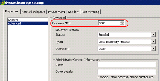
3. Click Advanced & change the ‘Status’ (Enabled), ‘Type’ (CDP/LLDP), & ‘Operation’ (Listen, Advertise, Both) as appropriate
a. CDP is typically for Cisco devices (proprietary) & LLDP is all other
vSS (per Host)
1. Open vCLI or desired cmd-line tool
2. CDP is the only protocol available for vSS and is in “listen” mode by default
3. To view the current Host CDP configuration: vicfg-vswitch –b vSwitch0
4. Change CDP config (options = both, advertise, listen): vicfg-vswitch –B both vSwitch0
5. Re-run cmd in Step 3 to verify the change took place
6. Using esxcli , view current CDP configuration of each vSwitch: esxcli network vswitch standard list
7. Change CDP config: esxcli network vswitch standard set –c both –v vSwitch2
2.2 – Configure & Maintain VLANs & PVLANs & Settings
Identify Types of VLANs & PVLANs
VLANs
1. There are 3 VLAN tagging methods (EST, VST, VGT) that can be used – see: http://kb.vmware.com/kb/1003806
PVLANs – can only be used on a vDS
1. Primary
2. Secondary:
a. Promiscuous
b. Community
c. Isolated
(above diagram used from Chris Wahl’s site (twitter: @chriswahl), wahlnetwork.com )
Determine Use Cases For & Configure VLAN Trunking
Traditionally, Trunking is configured on a pSwitch & is needed when sending multiple lines of VLAN traffic out a vSwitch/vmnic to a pSwitch Port
There is a VLAN Trunking setting that can be configured on a vDS PortGroup under > Edit Settings > VLAN > VLAN Type (drop-down)
Determine Use Cases For & Configure PVLANs (FANTASTIC video by none other than Mr. Eric Sloof: http://www.ntpro.nl/blog/archives/1465-Online-Training-Configure-Private-VLAN-IDs.html)
Primary & Secondary Configured on a vDS > Edit Settings > Private VLAN tab
1. Secondary PVLANs = Promiscuous, Community, Isolated
2. Only 1 Primary per PVLAN
3. Only 1 Promiscuous per PVLAN
4. Only 1 Isolated per PVLAN
Once configured, dvPortGroups can then be added (Edit Settings > VLAN > drop-down: PVLAN, then set the ‘Entry’)
Use Command-Line Tools to Troubleshoot & Identify VLAN Configurations
Use esxcli network and vicfg-vswitch commands
Examples (from previous section):
1. Enable VLAN: esxcli network vswitch standard portgroup set –p IPStorage1 –v 101
2. Disable VLAN: esxcli network vswitch standard portgroup set –p IPStorage1 –v 0
2.3 – Deploy & Maintain Scalable Virtual Network
Identify VMware NIC Teaming Policies (pg. 44 Network Guide)
Route Based on Originating Port ID – uplink chosen based on virt port where traffic entered the vSwitch
1. Default setting
2. Uplink selected based on virtual port where traffic entered the vSS
Route Based on IP Hash – uplink chosen based on hash of source & destination IP
1. Must be used with Etherchannel/LACP physical switch configuration
a. When using Etherchannel, only 1 EC configuration per vSS or vDS is allowed (see: http://kb.vmware.com/kb/1001938)
2. Cannot use Beacon Probing as Failover Mode; only Link Status
Route Based on Source MAC Hash – uplink chosen based on a hash of source ethernet
Use Explicit Failover – always use uplink highest in the list of active adapters
1. Uplink used is the first in the Active Adapters order list
Route Based on Physical NIC – vDS setting only; true load balancing based on pNIC in Active state
Other Policies:
1. Network Failover
a. Link Status Only – detects cable pulls & power failures, not config errors
b. Beacon Probing – *do not use with IP Hash
2. Notify Switches (Yes or No)
a. When a vNIC is connected to a vSS or the vNIC traffic is re-routed via different pNIC in the Team due to failover, a notification is sent to the network (pSwitch) to update lookup tables (Default = ‘yes’)
b. *Do not use with NLB Unicast Mode (Multicast has no issues)
3. Failback (Yes or No)
a. Failed adapter either returns to duty post-failure (‘Yes’), or remains as a Standby (‘No’)
4. Failover Order
a. *Do configure Standby NICs when using IP Hash Team Policy
Identify Network Protocols (see: http://kb.vmware.com/kb/1012382)
Most common:
1. 21 – FTP
2. 22 – SSH
3. 23 – Telnet
4. 53 – DNS
5. 80 – HTTP
6. 88 – Kerberos
7. 123 – NTP
8. 161 – SNMP (UDP)
9. 389 – LDAP
10. 443 – HTTPS; vSphere Client to vCenter & Host; vCenter to Host
11. 902 – Host to Host; Client to VM Console
12. 903 – Client to VM Console
13. 1234 – vSphere Replication
14. 2049 – NFS
15. 3260 – iSCSI
16. 5989 – CIM
17. 8000 – vMotion
18. 8100 – FT
19. 8182 – HA
20. 9000 – Update Manager
Understand NIC Teaming Failover Types & Related Physical Network Settings
See the 1st bullet above; pay attention to when/when not to use a Teaming or Failover policy setting (i.e. taking into account MS NLB, LACP, etc.)
Determine & Apply Failover Settings
This will be determined by design requirements. In using the 1st bullet above, some settings will be determined by the physical network (i.e. if using Etherchannel, IP Hash Load Balancing must be used, etc.)
Appying settings is as easy as going into the vSS, vSS PortGroup, or dvPortGroup settings and configuring Teaming & Failover:
Configure Explicit Failover to Conform to VMware Best Practices (pg. 75 Network Guide)
Active/Standby Configuration (notice Fig. 4 Active/Standby vmnic’s):
http://kb.vmware.com/kb/1002722
Configure PortGroups to Properly Isolate Network Traffic
Isolate traffic types (Mgmt, FT, IP Storage [i.e. iSCSI], VMotion, VM Netwk) with PortGroups & VLANs, or use dedicated pNICs
2.4 – Administer vDS Settings
Describe the Relationship Between vSS & vDS
vSS is local to an ESXi host; vDS is maintained by vCenter
A cached copy of a vDS is maintained by each host connected to the vDS & updated every 5mins
A “hybrid” scenario can be used (vSS with vDS, also with 3rd party Cisco Nexus 1000v)
Some differences are shared here: http://kb.vmware.com/kb/1010555
Understand the Use of Command-Line Tools to Configure Appropriate vDS Settings on a Host
The use of esxcli network dvs vmware has limited parameters for the vDS; vicfg-vswitch has some parameters that can be used
Determine Use Cases For & Apply Port Bind Settings (see: http://blogs.vmware.com/vsphere/2012/05/why-use-static-port-binding-on-vds-.html & http://kb.vmware.com/kb/1022312)
Static – default & recommended setting; assigned & retained to VM when connected to a port group
Dynamic – (not recommeded/deprecated with ESXi 5.x); allows virtual port overcommitment – assigned to VM at power on & disassociated when VM is powered off, or when the vNIC is connected/disconnected. These ‘states’ must take place in vCenter, not on the host directly
Ephermal – same as Dynamic but allowed to configure on hosts. Should only be used in recovery purposes
AutoExpand – new to 5.x; allows portgroup to auto-expand ports when ports are running low
Configure Live Port Moving
Not much in the way of this setting. Shows in Network Guide as being on pg. 26, but nothing shown
Given a Set of Network Requirements, Identify the Appropriate vDS Technology to Use
I’ve seen a couple blogs talk about using something “other” than vDS (i.e. Cisco Nexus 1000v) for this topic. I view this as ‘given a set of requirements, choose what vDS setting to use’. But, since the Cisco solution is a vDS, but 3rd-party-based, I recommend reviewing this info:
http://www.vmware.com/files/pdf/technology/cisco_vmware_virtualizing_the_datacenter.pdf
The main thing to take away from this is that you get more networking control with the Cisco solution
Configure & Administer vSphere Network I/O Control (see: Net I/O Best Practice Whitepaper, http://www.vmware.com/files/pdf/techpaper/VMW_Netioc_BestPractices.pdf & http://blogs.vmware.com/vsphere/2011/08/vsphere-5-new-networking-features-enhanced-nioc.html)
Enable – Go to Networking (CTRL+SHFT+N), select vDS on the left then Resource Allocation tab on right; click Properties link then select the box to enable NIOC
7 default traffic types (referred to as Network Resource Pools) – FT, iSCSI, Mgmt, NFS, VM, VMotion, vRep; custom/user-defined Pools can be created as well
Usability – shares are configured to control Network Resource Pool (type) bandwidth across a pNIC
Use Command-Line Tools to Troubleshoot & Identify Configuration Items from an Existing vDS
See the 2nd item in this section as well as 2.1
SECTION 3 3.1 – Tune/Optimize vSphere Performance
http://www.vmware.com/pdf/Perf_Best_Practices_vSphere5.0.pdf (page references listed below)
Identify BIOS & Firmware Setting Requirements for Optimal ESXi Host Performance (pg. 14)
It is an industry best practice to, upon receiving your server, update your BIOS and all firmware
BIOS Configurations:
1. Enable all populated CPUs
2. Enable Turbo Boost
3. Enable Hyper-Threading
4. Enable Intel-VT, EPT, & VT-d (I/O MMU) or AMD-V, RVI & Vi (I/O MMU)
5. Disable unused devices (i.e. Floppy, Serial, USB, NIC, LPT)
6. Disable Node Interleaving
Identify Driver Revisions Required for Optimal ESXi Host Performance
Well, not sure about “optimal” as much as what should be here, which is “supported”. VMware’s HCL can be checked for I/O devices (storage controllers, NICs, CNAs, HBAs) and from there, the device link listed can be clicked on & the device driver version verified for support of the ESXi version.
Tune ESXi Host Memory Configuration (pg. 25-28)
Configuring VM memory appropriately leads to reduction of overprovisioning memory (thus having more available for other VMs & thus optimizing consolidation ratios); also leads to reduction of negative VM performance impact due Host minimizing need to reclaim memory elsewhere and/or prevent swapping to disk. Overcommitment is handled 5 ways:
1. TPS
2. Ballooning (by way of vmemclt driver in VMware Tools)
3. Compression
4. Swap to Cache (using local SSD)
5. Swap to Disk
ESXi supports large memory tables but doesn’t use TPS for guests enabled for large pages (2MB)
Tune ESXi Host Networking Configuration (pg. 34-36)
Items to be aware of:
1. DirectPath I/O
2. Network I/O Control – 7 default Resource Pools: FT, iSCSI, Mgmt, NFS, VM, VMotion, vRep
a. User-defined Pools
b. Best used with CNA’s
3. Use separate vSwitches with different pNICs to reduce contention amongst traffic types
4. Use VMXNET3 adapter
5. For Network Latency applications, change Power Mgmt to High Performance (default = Balanced)
6. Use Jumbo Frames (config on PortGroups) with IP Storage if supported
7. SplitRx Mode
a. Enable by setting VM’s .vmx ethernetX.emuRxMode value to 1 (‘X’ represents the number of the vmnic)
b. Only capable when using VMXNET3 adapter
Tune ESXi Host CPU Configuration (pg. 19-24)
Always start with 1 vCPU unless an app specifically calls for more (i.e DB apps such as SQL & Exchange)
Enable Hyperthreading – first in the BIOS, then on each host (Host > Configuration tab > Processors > Properties link)
1. Verify VM Advanced CPU setting – Edit Settings > Resources > Advanced CPU > “Any”
NUMA – disable Node Interleaving in the BIOS to
enable this feature
1. Configure VM vCPUs in multiples of the total cores in the Host to retain vCPU processes on the same NUMA node
Tune ESXi Host Storage Configuration (pg. 29-33)
Enable Storage I/O Control for all Datastores (Rt-click on Datastore > Properties > select Enable SIOC)
1. Must use vCenter
2. No multi-extent Datastores
3. Default ms threshold metric is 30ms
4. To set VM disk “share” – Edit (VM) Settings > Resources tab > Disk, adjust shares accordingly
Right-size your backend storage for the load (IOPS) of your VMs (covered more in depth in Obj. 1.1)
Set MPIO (SAN Multipathing Policy) according to SAN vendor recommendations:
1. Active/Active = Fixed PSP
2. Active/Passive = MRU PSP
3. ALUA = no set ‘default’, but MRU or RR PSPs are generally used
Enable Storage DRS
1. Maximums – 32 Datastores per Cluster; 256 Clusters per vCenter
2. Clusters must contain “like” type Datastores (i.e. all NFS or all VMFS, etc.)
Use storage enabled with VAAI
Align disks properly
Use Jumbo Frames with IP Storage if supported
Use pvscsi adapter for data disks
Configure & Apply Advanced ESXi Host Attributes (pg. 101-104 Resource Mgmt Guide)
Host > Configuration tab > Software ‘box’ > Advanced Settings, then select the appropriate heading (i.e. Cpu, Mem, VMkernel, UserVars, etc.)
Configure & Apply Advanced Virtual Machine Attributes (pg. 104-105 Resource Mgmt Guide)
Edit Settings > Options tab > Advanced > General > Configuration Parameters button, then click to Add a Row
Since this usually changes the vmx file, a reboot of the VM typically needs to be performed before the change takes affect
Configure Advanced Cluster Attributes
HA: Rt-click Cluster > Edit Settings > HA > Advanced Settings
DRS: Rt-click Cluster > Edit Settings > DRS > Advanced Settings
See pg. 28-29 of Availability Guide for HA Attributes
3.2 – Optimize Virtual Machines
Compare & Contrast Virtual & Physical Hardware Resources
I think the 2 biggest takeaways from this are ability to overcommit as well as “resource allocate” (share, reserve, limit) virtual resources as compared to physical resources
Identify VMware Memory Management Techniques
Overhead – based upon # of vCPUs & Configured RAM for a VM
Memory Reclamation Techniques
1. TPS
2. Ballooning
a. Idle Memory Tax – VMkernel reclaims up to 75% of idle/unused allocated
shares (can be configured for different % value); see: http://boche.net/blog/index.php/2009/01/29/idle-memory-tax (twitter: @jasonboche)
b. Enabled by default upon installation of VMware Tools
3. Compression – memory condensed into 2KB pages stored in VM compression cache
4. Swap to Cache
a. Configurable with vSphere Client for each Host (Configuration tab > Software box > Host Cache Configuration)
5. Swap to Disk
a. Cluster > Edit Settings Swapfile Location
b. If using ‘Store the swapfile in the Datastore specified by the Host’, you will then need to click on the Host(s) in the Cluster > Configuration tab > Virtual Machine Swap Location, & select a Datastore
* NOTE: 2 Techniques used during contention are Ballooning & Swap; other Techniques run regardless of contention
Identify VMware CPU Load Balancing Techniques
When a CPU, or at least 1 of its cores, gets saturated, the ESXi Host CPU Scheduler will transfer processes (“worlds”) to less active/saturated cores
During times of contention, VM shares will be taken into account
Hyperthreading is a CPU feature that allows a single core to run 2 logical ‘threads’
1. Enable first in the BIOS of each Host, then in vCenter – Host > Configuration tab > Processors link in the Software box, Properties
Balancing or ‘best performance’ is also handled by NUMA
Identify Pre-Requisites for Hot-Add Features
Only specific OS Support
1. Memory Hotplug is supported on ALL x64 bit systems
Virtual Hardware 7 or greater
1. For SMP vCPUs, Virtual Hardware 8 is required
VMware Tools must be installed
To Enable – power off VM, Edit Settings > Options tab > Memory/CPU Hotplug
Tune Virtual Machine Memory Configurations
Don’t overcommit/undercommit such that swapping occurs
Install VMware Tools so during times of memory contention, the balloon driver can be used
Resource Allocation – Shares, Reservations, & Limits should rarely be used. Using Shares is most recommeded of all options & Limits is least recommeded
Install an SSD-backed Datastore for Swap to Host Cache use
Tune Virtual Machine Networking Configurations
If needed, install multiple vNICs to isolate or segregate traffic
Use VMXNET3 adapter
1. Requires Virtual Hardware 7
2. Requires VMware Tools
3. Ensure Guest OS support (XP & higher; see: http://kb.vmware.com/kb/1001805)
Enable Jumbo Frames (MTU = 9000) for IP Storage
Tune Virtual Machine CPU Configurations
For Hyperthreading, ensure VM ‘mode’ is set to “Any” (covered in Obj. 3.1)
Use uniprocessor HAL for single-threaded apps and multi-processor HAL for multi-threaded apps
If hosts are NUMA-capable, verify VM Virtual Hardware version is 8 so the Guest is exposed to NUMA for NUMA-aware apps (virtual NUMA)
Hiding NX/XD flag from the Guest increases VMotion performance but may disable certain CPU security features
Tune Virtual Machine Storage Configurations
Separate virtual disks of VMs when possible (i.e. OS vs Data)
Use Paravirtualized SCSI for Data disks only
1. Requires Virtual Hardware 7
2. Typically only needed if I/O > 2000
Align disks throughout the storage ‘chain’ – backend (SAN; may be done automatically), Datastores (if added via vSphere Client, alignment is done automatically), within the Guest OS
Configure Guest (VM) registry to be able to handle large I/O requests
Use Disk Shares (SIOC) when appropriate (Edit Settings > Resources tab > Disk)
Calculate Available Resources
Cluster Resources: Summary tab > vSphere DRS box > Resource Distribution link to view CPU & RAM in % or MHz/MB
Host > Summary tab > Resources box to view CPU & RAM Host utilization
1. Can also use ESXTOP
2. CPU Metrics:
a. %PCPU USED –% of each physical core utilized by the logical core multiplied by “turbo mode”
b. %PCPU UTIL – % utilization of logical cores
c. %USED – % of pCPU core cycles used by a group of ‘worlds’ (processes)
d. %SYS – % of time spent in the VMkernel processing requests
e. %RDY – % of time the group was ready to run but CPU resources not available to handle requests
f. %WAIT – % of time the group was in a clocked or wait state
3. RAM Metrics:
a. PMEM/MB – amount of pMEM installed; PMEM represents amt of RAM actively used by the Host; vmk represents amt of RAM used by the VMkernel; Free = how much Host RAM free to service requests
b. VMKMEM/MB – rsvd & ursvd (reserved/unreserved)
c. NOTE: PMEM free should be higher than VMKMEM ursvd
4. VM Resources: VM > Resource Allocation tab; Allocated, Consumed, Ballooned, & Active utilization
Properly Size a Virtual Machine Based on Application Workload
See Obj. 1 – I think this is basically saying calculate IOPS required for a VM, add total IOPS of all VMs, then configure & right-size the backend storage needed to meet the IOPS requirement. Take into account Write penalty. Also, don’t overcommit vCPUs or Memory
Modify Large Memory Page Settings (pg 102 Resource Mgmt Guide)
Configured on a per-Host basis: Host > Configuration tab > Software box > Advanced Settings link > LPage & Mem objects. Configure appropriate setting based on screenshot below:
Understand Appropriate Use Cases for CPU Affinity
Assigning CPU logical processor (hyperthreaded system) or core (non-hyperthreaded system) to a VM
Use Cases:
1. Maybe legacy applications
2. Simulating workload/load testing an app
Limitations:
1. NUMA may not be able to manage VMs with CPU Affinity
2. Hyperthreading may not be utilized by VMs with CPU Affinity
3. Reservations and/or Shares may not be fully respected
4. VMotion/Migration to other hosts may disable the CPU Affinity
NOTE: Cannot assign affinity to a VM in a DRS Cluster or if Host only has 1 processor CORE (Affinity setting won’t show; Edit Settings of VM > Resources tab > Advanced CPU)
Configure Alternate Virtual Machine Swap Locations
VM > Edit Settings > Options > tab, Swapfile Location
1. If multiple VMs can use same location, reconfigure the Cluster, then each Host; the default option for VMs is to use Cluster or Host settings; change this only if needed
3.3 – Implement & Maintain Complex DRS
Explain DRS/Storage DRS Affinity & Anti-Affinity Rules
DRS
1. VM-VM (pg 74-75 Resource Mgmt) – VMs should be on same Host or not
2. VM-Host (pg 73-74 Resource Mgmt) – VM(s) must/must not or should/should not be associated with a Host
a. VM Group & Host Group needs created before creating this Rule as this Rule uses both Groups
3. Both 1 & 2 above can be Affinity & ANTI-Affinity
SDRS
1. Intra-VM – VMDKs of VM kept on same Datastore (this is a ‘default’; Rules can’t be set, just the ‘option’ in VM Settings of a Datastore Cluster)
2. Intra-VM Anti – VMDKs of VM not on same Datastore
3. Inter-VM Anti – VMs not on same Datastore
4. NOTE: Invokation upon initial placement & recommendation, not via Manual user run of SDRS
Identify Required Hardware Components to Support DPM (pg. 67 Resource Mgmt Guide)
Dependent upon hardware
All configuration is pretty much done in the BIOS or web-interface for the specific technology (IPMI) used
1. IPMI, iLO (HP), or WoL can be used
2. BMC for IPMI is ‘always on’ & invokes the power-on operation; uses MD5 authentication
WoL capability/support can be viewed via Configuration tab > Network Adapters link, WoL Support
1. pNIC associated with VMotion VMkernel PortGroup must support WoL (can check Network Adapters)
Identify EVC Requirements, Baselines, & Components (pg. 119 vCenter & Host Mgmt Guide)
Requirements:
1. Same vendor (Intel or AMD) CPU
2. ESXi 3.5 U2 or later
3. vCenter
4. **VMs with CPU feature set GREATER than EVC mode must be powered down
5. BIOS – enable Intel-VT/AMD-V & Intel-XD/ AMD-NX
6. Check VMware’s HCL for CPUs compatible with the EVC mode wanting to configure for
Baselines
1. See: http://kb.vmware.com/kb/1005764 for info & Baselines (for Intel & AMD)
Understand DRS/SDRS Migration Algorithms, Load Balance Metrics, & Their Impact on Migration Recommendations
DRS
1. Invoked every 5mins (300secs)
2. Before load balance recommendations, constraints (rules violations) are taken care of
3. Imbalance occurs when CHLSD > THLSD (based on 1-5 migration threshold setting)
a. Imbalance causes: VM resource setting change, host added/removed from Cluster, host enters/exits Maintenance Mode, moving VM in/out of Cluster
b. DRS determines cost-benefit-risk & if not exceeded, a recommendation is made
SDRS
1. Invoked every 8hrs
a. And when: manually, placing a Datastore in Datastore Maintenance Mode, moving a Datastore in a Datastore Cluster, Datastore space threshold is exceeded
2. Before load balance recommendations, constraints (rules violations) are taken care of
3. Load balance recommendations are based off I/O latency & space utilization Cluster configurations, as well as % differential between source & target Datastore
4. SDRS determines cost-benefit-risk & if not exceeded, a recommendation is made
Properly Configure BIOS & Management Settings to Support DPM (pg. 69 Resource Mgmt Guide)
See 2nd bullet above
IPMI/iLO/WoL settings should be configured in the BIOS
IPMI uses a BMC
1. BMC should be configured with IP & acct for power-on action
2. Enter this BMC info in vCenter: Host > Summary tab > Software box > Power Management link, Properties link
Test DPM to Verify Proper Configuration (pg. 70 Resource Mgmt Guide)
Cluster > Edit Settings > DRS > Power Management and select ‘mode’ and threshold level
In vCenter, rt-click host > Enter Stand-by Mode; once in Stand-by, rt-click > Power On
1. Requires VMs to be migrated to other Hosts or Powered Off
NOTE: If test fails, Edit Cluster > vSphere DRS > Power Management > Host Options & Disable DPM for the Host
Configure Appropriate DPM Threshold to Meet Business Requirements (pg. 71 Resource Mgmt Guide)
Off
Manual – no automation of anything; vCenter only gives recommendations
Automatic – vCenter places hosts in ‘Standby’ (power-off) mode based on DPM Threshold configured
1. Threshold – Conservative > Aggressive (Priority 1-5)
a. Conservative (Priority 1) only deals with power on, not power off
b. Priority 1 is a mandatory setting while Priority 5 will only bring slight improvement
2. Can granularly change Pwr Mgmt per Host but not threshold level per Host
Configure EVC Using Appropriate Baselines (pg. 120 vCenter & Host Mgmt Guide)
Baselines = EVC ‘Modes’ ; see 3rd item in this section for requirements
Enable – Create an empty cluster, Enable EVC in Cluster Settings, then move Hosts into the Cluster (recommended method)
1. 2nd method to enable – power off VMs on Hosts with higher feature set, enable EVC, power on VMs
2. VMs with higher CPU feature set need to be powered down (NOT a reboot), then powered on whether creating an empty EVC Cluster or enabling EVC on existing Cluster
Change EVC Mode on Existing DRS Cluster (pg. 121-122 vCenter & Host Mgmt Guide)
One thing to keep in mind is when changing the Mode (Baseline), VMs may or may not (i.e. elevating a Baseline) need to be powered down. But, if VMs do not need to be powered down for the change, they do eventually need powered down then back on for the new (elevated or degrated) feature set to take affect
To check VM EVC Mode, select Cluster > Virtual Machines tab, then look for the EVC Mode column; if column is not shown, rt-click the columns and choose ‘EVC Mode’ column from the list
Create DRS & DPM Alarms
Click on the appropriate object Alarm is to run against, in this case the Cluster object > Alarms tab > Definitions button; rt-click in white space > New Alarm & configure as needed
DRS
1. Alarms exist for both Cluster & Host, with the ‘Specific events’ option (not ‘State’)
DPM
1. Most serious alarm should probably configure is “Exit Standby Mode” error, & is already created by default so just enable the trigger action
2. To create, use a Host Alarm, not Cluster, with ‘Specific events’ option selected (not ‘State’)
Configure Applicable Power Management Settings for ESXi Hosts
Per Host configuration – Host > Configuration tab > Hardware box > Power Management link, Properties hyperlink
1. High Performance – maximum performance using no power mgmt features
2. Balanced – (default) reduce Host power consumption while having little/no impact on performance
3. Low Power – aggressively reduces Host power consumption at risk of performance
4. Custom – same as Balanced, but allows modification
Cluster (DPM)
1. Edit Cluster > vSphere DRS > Power Management > Host Options, set options as ‘Default (Cluster setting)’, ‘Disabled’, ‘Manual’, or ‘Automatic’
Properly Size Virtual Machines & Clusters for Optimal DRS Efficiency
Ensure Hosts have consistent configuration (same CPU, CPU feature set, RAM amount)
Adhere to Cluster maximums – 32 Hosts/Cluster; 3000 VMs/Cluster
Avoid VM-Host Affinity “Must” Rules
Don’t change Automation Level per VM if at all possible
Don’t oversize/over-reserve VM resources
Re-review 3.2 & various parts of Obj. 1
Properly Apply Virtual Machine Automation Levels Based on Application Requirements
Edit Cluster > vSphere DRS > Virtual Machine Options, set Automation Level for specified VM as ‘Default (Cluster setting)’, ‘Fully Automated’, ‘Partially Automated’, ‘Manual’, ‘Disabled’ (pg. 59-60 Resource Mgmt Guide)
Use case – VM app(s) may need to be associated with a certain Host (e.g. Serial security device)
Create & Administer ESXi Host & Datastore Clusters
See Obj. 1.2 (last item) for Datastore Cluster creation
Host DRS Cluster – pg. 58 Resource Mgmt Guide; Cluster req’s on pg. 57-58 (section begins on pg. 53)
1. Most items have been discussed in this section; creating a Cluster is pretty straightforward…understand Cluster settings then configure based on business requirements
Administer DRS/Storage DRS
DRS
1. Affinity/Anti-Affinity Rules
a. VM-VM – VMs on same Host or not (anti)
1) Cluster > Edit Settings > vSphere DRS > Rules > Add button, name the rule, select the option (Keep VMs together, Separate VMs), click Add button and select the VM(s)
b. VM-Host – VM must/should be on a certain Host or not (anti)
1) Cluster > Edit Settings > vSphere DRS > DRS Groups Manager > Add button, name the VM Group, click Add button to select the VM(s); repeat for adding Hosts
2) Cluster > Edit Settings > vSphere DRS > Rules > Add button, name the rule, select the option Virtual Machine to Hosts, add the VM & Host Groups, then select 1 of 4 options: Must/Must Not run or Should/Should Not run option
2. Add/Remove Hosts
a. Add: Rt-click on Cluster > Add Host
b. Remove: Host must be in Maintenance Mode, which means VMs either need migrated off or powered down
1) VMotion VMs to another Host, place Host in Maintenance Mode, drag Host to Datacenter object
3. Cluster Validation (Overcommitted [yellow]/Invalid [red])
SDRS
1. Used with Datastore Clusters (Home > Inventory > Datastores & Clusters)
2. Before SDRS can be used, make sure to Enable it if not already done so during Datastore Cluster creation
3. Affinity/Anti-Affinity Rules – see above
4. Maintenance Mode
a. Datastores & Datastore Clusters > rt-click Datastore > Enter SDRS Maintenance Mode
b. NOTE: VMDKs must be migrated to other Datastores before Maint Mode can successfully proceed
5. Scheduling
a. Datastores & Datastore Clusters > rt-click Cluster > Edit Settings > General tab, check to Enable SDRS; other option is to select Cluster > SDRS tab > Edit hyperlink
b. Use scheduling to minimize performance hits that could occur during business for VMDK moves
6. VM Settings
a. Cluster > Edit Settings > Virtual Machine Settings, select Automation Level and/or VMDK Affinity/Anti-Affinity
b. From Cluster > Edit Settings > Rules, VMDK & VM Anti-Affinity Rules can be config’d
7. Migrations
a. Datastore Cluster > SDRS tab – can run SDRS manually and/or apply recommendations from here
3.4 – Utilize Advanced vSphere Performance Monitoring Tools
Identify Hot Keys & Fields Used With resxtop/esxtop
C = CPU,
D = Disk Adapter,
M = Memory,
N = Network,
P = Pwr Mgmt,
U = Disk Device,
V = Disk VM
1. NOTE:
F = modify columns used;
O = modify column order;
S = modify refresh time in sec’s
2. When in a ‘mode’ (CPU, Adapter, etc.), you can sort by certain headings (READ, WRITE, etc.) by using a capital or small
R/
r (read) or
T/
w (write); default sort can be returned by capital
N 3.
s for refresh interval in seconds &
q to quit
Identify Fields Used With vscsiStats
See below (‘Using vscsiStats‘ item)
Configure resxtop/esxtop Custom Profiles (pg. 60 Monitor & Perf Guide)
SSH to Host, go through each display (c, d, m, etc.) and modify the view as desired; when done type
W, then type the path & name of the modified config/views (i.e. /tmp/.vcap5conf)
To run the custom profile, type: esxtop -c /path/to/filename.conf
Determine Use Cases For & Apply resxtop/esxtop Interactive, Batch, & Replay Modes
Interactive Mode – (default Mode) Real-time Host monitoring; typing esxtop is all that’s required (pg. 46 Monitor & Perf Guide)
Batch Mode – Used to track metrics over time (history) down to 2second intervals (vCenter = 20sec’s); (pg. 60 Monitor & Perf Guide)
1. -b = batch mode, -d = delay in seconds, -n = number of iterations (x delay = total), > = export filename
2. Sample command: esxtop -b -d 2 –n 400 > vcap5dcabatch.csv.gz
Replay Mode – Capability to use a vm-support generated “bundle” to run esxtop against (pg. 61 Monitor & Perf Guide)
1. -p = collect performance snaps, -i = collection interval in secs, -d = duration
2. Generate a Support Bundle: vm-support -p -i 10 -d 60 (see: http://kb.vmware.com/kb/1967)
3. The path of the bundle will be displayed when the task is completed (i.e. /var/tmp/….)
4. cd to the path displayed & then unpack the newly created file: tar -xzf /var/tmp/NameOfFile.tgz
5. Reconstruct files (may be needed): cd /var/temp/<path of bundle>, then type: ./reconstruct.sh
6. Enter Replay Mode: esxtop –R /var/tmp/<path of bundle>
Use vscsiStats to Gather Storage Performance Data (see: http://communities.vmware.com/docs/DOC-10095)
Get worldGroupID of the VM wanting to collect data against: vscsiStats -l
Start the collection: vscsiStats -w 811625 –s (runs on ALL VMDKs of the VM with ID 811625)
1. vscsiStats -w 811625 -i 8422 –s (runs on specific VMDK [8422] of the VM)
2. To view onscreen: vscsiStats -w 811625 -i 8422 –p all (or ioLength, seekDistance, latency, instead of ‘all’)
3. To export to a file: vscsiStats -w 811625 -i 8422 –p all -c > /tmp/vcap5vscsiStats.csv
4. To stop vscsiStats collection on ALL VM disks: vscsiStats -w 811625 -x
5. See here: http://www.vmdamentals.com/?p=722, for a tool to import the stats in a 3D chart
Use resxtop/esxtop to Collect Performance Data
Only way to collect data with esxtop is to use Batch Mode, covered above
To run a 5-second interval (i.e. delay) collection for 10mins – determine the “iteration” (i.e. -n) by using this formula: ([minutes x 60] / delay) → ([10 x 60] / 5) = 120, so:
esxtop –b –d 5 –n 120 > /tmp/vcap5dcabatch.csv
Given resxtop/esxtop Output, Identify Relative Performance Data for Capacity Planning Purposes
Interpreting CPU metrics → see: http://kb.vmware.com/kb/1017926
1. PCPU UTIL% - Avg below 60%
Memory
1. State – High (> 6% Memory Free), Soft (4-6% Free), Hard (2-4% Free), Low (< 2% Free)
a. High = good…sufficient free memory to where Host not under contention
b. Low = bad…minimal amt of free memory left; Host is in contention
2. MEMCTL/MB – if above 0, ballooning is going on; some ballooning is normal…consistent is not
3. SWAP/MB – if above 0, swapping is going on (State is typically at Hard or Low)
a. r/s and w/s should be close to 0
Disk
1. Determine IOPS per VM by looking at READS/s & WRITES/s
2. DAVG (latency ouside the guest/hypervisor) – typically > 15ms
3. KAVG (VMkernel) – typically > 1ms
4. GAVG (guest; DAVG + KAVG)
SECTION 4 4.1 – Implement & Maintain Complex HA Solutions
Identify 3 HA Admission Control Policies
Host Failures Cluster Tolerates
1. Uses slot sizes – logical “constructs” of CPU & Memory
a. Take largest CPU Reservation & Memory Reservation of all VMs on a Host
1) Default Reservation if none configured: CPU = 32MHz ; Memory = 0MB + Overhead
b. Divide Total Host CPU by largest CPU Reservation & Total Host RAM by largest RAM Reservation
c. The SMALLEST value of the 2 (of CPU & RAM) = # of slots of the Host
1) Round the number down for fractions
d. View slot info: Cluster > Summary tab > vSphere HA box, Advanced Runtime hyperlink (
NOTE: the Advanced Runtime hyperlink isn’t shown if this HA Policy isn’t used); pg. 17-18 Availability Guide
1) Used Slots = Slots used by powered on VMs
2) Failover Slots = Total Cluster Slots/# of Hosts Configured for failover for this Policy (assuming all Hosts have same Resource CPU/Memory configurations)
3) Available Slots = Total Cluster Slots – Used Slots – Failover Slots; this # is the amt of slots available to power on
additional VMs in the Cluster while taking into acct failover capacity
2. NOTE: Slots may be ‘fragmented’ for VMs; i.e. if a VM requires > 1 slot and a Host can’t support it, but multiple Hosts can, the power on operation will still fail; DRS may be able to resolve this fragmentation
Percentage of Cluster Resources Reserved as Failover Spare Capacity
1. Can configure CPU & Memory % separately
a. Typically, can calculate using 1/N formula (or 2/N; N = total Hosts in Cluster), or Total Host Resource – Resource Requirement (i.e. currently used or amt desired to be reserved) / Total Host Resource
2. Current Failover Capacity % = Total Host Resource – Total Used Resource / Total Host Resource (configured for each resource, CPU & Memory)
NOTE: Current Failover Capacity = how many Hosts can fail & still have enough slots leftover to failover currently powered-on VMs
a. Current Failover (free) Capacity % – Configured Capacity % for Admission Control (CPU or RAM) = amt of resources % available to power on additional VMs
b. 100% – Current Failover % = % resource free needed on another Host to successfully failover all powered on VMs
c. Process:
1) Total required resources currently used by powered on VMs in the Cluster
2) Total aggregate Host resources available in the Cluster
3) Current CPU & Memory Capacity (free capacity) calculated: ([Res Total-Used Res]/Res Total)
4) If the “current” is less than what is “configured” for HA Adm Ctrl, VMs will not be allowed to power on. In this case, too many VMs have been provisioned in the Cluster to honor the configured failover capacity
Specify Failover Host(s)
1. Pre-vSphere5 could only specify single Host; now can specify multiple Hosts
2. Host cannot be used by any VMs at any time except in the event of a failed Host
Identify Heartbeat Options & Dependencies
Network
1. Uses Mgmt VMkernel PortGroup – Slaves send heartbeats to the Master & Master to the Slaves every 1 second (there are no ‘slave-to-slave’ heartbeats)
Datastore (New to vSphere 5)
1. Extra redundancy layer to prevent false positives of Network Heartbeating
2. When Network Heartbeats stop, this is used
3. 2 Datastores are used by default, but Advanced setting can increase amt of Dastastores used, or can manually assign Datastores (though not recommended)
a. Datastore must be connected to all Hosts in the Cluster
b. VMFS chosen over NFS if possible
c. Datastores selected on different SANs if possible
4. Uses a “protectedlist” file on each selected heartbeat Datastore
Calculate Host Failure Requirements
Host Failures Tolerates example (each step listed should be accomplished separately for CPU & RAM)
1. Add total resource of all Hosts in the Cluster
2. View resource reservation of all VMs in the Cluster
3. The LARGEST resource reservation is the value of the ‘slot’ size for that resource
4. Divide total Cluster resource by the the largest VM reservation to attain number of slots available for each resource (if a fraction, round down)
5. The SMALLEST value attained in Step 4 is used to determine number of slots per Host
6. Multiply the slots per Host value attained in Step 5 by the number of Hosts entered in this Policy to determine total slots needed for failover
7. NOTE: If you have heterogenous Hosts in the Cluster, resource-wise, larger-sized Hosts slot calculation (slot size would thus be larger) will be dismissed…again..because HA uses conservative calculations to ensure failover
Percentage Cluster Resources example (each step listed should be accomplished separately for CPU & RAM)
1. Total each resource in the Cluster
2. Total each resource used in the Cluster
3. Calculate % available for each resource: Total of resource – Used of resource / Total of resource
4. Available resource – Configured resource = what is left to power on VMs
5. Example 1 – On avg, a 4-Host Cluster should have each Host not > 75% utilized to account for 1 Host failure (i.e. 1 out of 4 hosts failing = 25% free capacity)
6. Example 2 – Total the current used resources and divide by total Cluster resources to attain the current used %. This used % should be the minimum value used for the resource (CPU% or Memory %) for Admission Control (to account for growth, add more to this value)
Configure Customized Isolation Response Settings
Typically for each VM
Cluster > Edit Settings > vSphere HA > Virtual Machine Options, select Host Isolation Response from the drop-down (Use Cluster, Leave Powered On, Power Off, Shut Down)
Advanced Settings: Cluster > Edit Settings > vSphere HA > Advanced Options button
1. das.isolationaddress(#) – can add up to 10 (i.e. ‘#’) gateway addresses
2. das.usedefaultisolationaddress – true (1) or false (0)
3. das.isolationshutdowntimeout – specifies amount of time (in sec’s) to wait for a guest shutdown process before HA forceably power’s off a VM
Configure HA Redundancy
Mgmt Network (2 Options)
1. Add a 2nd vmnic to vSS and configure it as a Standby
2. Add a new vSwitch with VMkernel Mgmt Network PortGroup
Datastore Heartbeat
1. Redundant already (min of 2 get created)
2. Advanced Setting: das.heartbeatDsPerHost to have more than 2 Datastores used for heartbeating (but limit is 5)
Network Partitions – hmm…my guess is since this is a ‘bad’ thing to have happen, configure the above 2 for redundancy to avoid this from happening
Configure HA Related Alarms & Monitor an HA Cluster
Alarms – There are 5 default alarms as well as some that can be newly created
1. Alarm type will depend on business requirement
Monitor – Cluster > Summary tab, then HA or DRS section and click various hyperlinks (Cluster Status, Runtime, etc.)
1. Logs to check – fdm.log & hostd.log, both located in /etc/vmware
Create Custom Slot Size Configuration (pg. 28 Availability Guide)
2 options can be added in Cluster > Edit Settings > vSphere HA > Advanced Options button
1. das.slotCPUInMHz – maximum of CPU slot; actual slot value used by HA is the SMALLER between this value & largest VM CPU Reservation in the Cluster
2. das.slotMemInMB – maximum of Memory slot; actual slot value used by HA is the SMALLER between this value & largest VM Memory Reservation in the Cluster
Understand Interactions Between DRS & HA
After an HA failover, DRS can then take over to load balance
DRS won’t migrate VMs that violate HA Admission Control Rules
HA will ask DRS to defragment Cluster resources so a VM that requires resources that span > 1 Host can be powered on
Analyze vSphere Environment to Determine Appropriate HA Admission Control Policy (pg 21 Availability Guide)
Host Failures Cluster Tolerates – not concerned about fragmentation, yet can be overly conservative for Cluster heterogeneity
Percentage of Cluster Resources – flexible & dynamic, yet doesn’t address fragmentation
Specify Failover Host(s) – this is about availability. If an org can afford to have a Host stand by as ‘idle’, then use this Policy. No VMs can be used on this Host…it can & will only be used in the event of a Host failure
Analyze Performance Metrics to Calculate Host Failure Requirements
Looking at the Performance tab for Cluster, VMs & Hosts can give a realistic idea of consumed/available resources
Analyze Virtual Machine Workload to Determine Optimum Slot Size
Cluster > Virtual Machine tab, ‘Reservation – MB’ column (may need to be added) – if there is 1 or 2 VMs with elevated Reservation, a custom das.sloteMemInMB should be configured to enable more slots/host
Analyze HA Cluster Capacity to Determine Optimum Cluster Size
Not sure what is needed here, aside from monitoring VM memory & CPU to properly right-size for slots if Host Failures Policy is used, or total resources utilized by VMs to be able to set a minimum % for the Percentage Policy
4.2 – Deploy/Test FT
Identify FT Hardware Requirements
Licensed (Standard and above)
SiteSurvey Utility can show compatibility for VMware technology including FT: http://www.vmware.com/download/shared_utilities.html
Hosts with FT VMs should have virtually the same CPU
Use HCL to determine if Host is FT-compatible
BIOS – enable Intel-VT/AMD-V if not already
Identify FT Compatibility Requirements (pg. 38-39 Availability Guide)
2 Hosts have access to same Datastore FT VM(s) are on
Enable Host Certificate Checking: Home > Administration > vCenter Server Settings > SSL Settings option, select vCenter Requires Verified Host SSL Certificates
FT Logging Network/PortGroup
VMotion PortGroup
HA-enabled Cluster
Host
1. License: Standard & above
2. Similar processors (frequency)
3. HV enabled in BIOS
4. FT/VMotion Networks created
5. Power Mgmt/Hyperthreading configured consistently across FT Hosts
VM
1. On shared storage accessible by both Hosts
2. 1 vCPU
3. Eager-Zeroed Thick Disk or virtual RDM
4. Supported OS (see: http://kb.vmware.com/kb/1008027)
5. No snapshots
6. No backups (vAPI-DP)
7. No paravirtualization (VMXNET3/PVSCSI)
8. No NPIV
9. No Storage VMotion
10. No Hot-plug
11. No CD, Serial, 3D, IPV6, or USB devices
Cluster > Profile Compliance tab, Check Compliance Now hyperlink to test FT compatibility
Modify VM & ESXi Host Settings to Allow FT Compatibility (pg. 44 Availability Guide)
FT can be used with DRS only if EVC is also enabled
1. VM-VM Affinity Rule applies only to Primary VM
2. VM-Host Affinity Rule applies to both Primary & Secondary VM
Configure two networks – VMotion & FT Logging
1. Use 2 pNICs if possible
Shared Storage by both Hosts used for FT VM
BIOS Settings
vCenter SSL enabled
vCenter – if Cluster is also a DRS Cluster, make sure EVC is enabled
VM has no snapshots
VM has 1 vCPU
VM has no physical RDM, only virtual RDM or Eager Thick disk
See other req’s above
Cluster > Profile Compliance tab > Check Compliance; for any Host that fails compliance, use Host > Summary tab > General box, then click ‘Host Configured for FT’ info link (see below) to display issues
needing to address:
Use VMware Best Practices to Prepare for FT Use (pg. 47 Availability Guide)
At least a 3-Host HA Cluster running ESXi 4.0 or greater
10GbE for FT Logging with Jumbo Fames configured
No more than 16 VMDKs per FT VM
Avoid Network Partitions
Same ESXi version
Same VM Network configuration
Same/compatible Host processors
No more than 4 FT VMs per Host
Have a Host upgrade plan (migrate primary & secondary VM to 2 other Hosts, upgrade both orig Hosts, disable FT, migrate primary VM back to now upgraded Host, turn FT back on)
Configure FT Logging (pg. 41-42 Availability Guide)
Host > Configuration tab > Hardware box > Networking link, vSwitch Properties hyperlink, Add a VMkernel PortGroup & check ‘Use This Port Group for FT Logging’
1. Should be dedicated vmnic if possible
Prepare for FT Compliance
Use Profile Compliance tab or (if failed) use Summary tab for each Host, FT info link to correct any issues
Test FT Failover, Secondary Restart, & Application FT in a FT Virtual Machine
Once all above validations are met, turn on FT:
1. Power down VM using for FT
2. Rt-click > Fault Tolerance > Turn on Fault Tolerance
3. Read ‘info’ messages & be aware that a reservation equal to config’d VM memory is created
4. Click ‘Yes’ to enable FT
5. When complete, rt-click VM > Power > Power On
6. Verify FT protection via VM’s Summary tab
Test Failover:
1. Rt-click VM > Fault Tolerance > Test Failover
2. Takes several minutes – monitor from Primary VM Summary tab
3. Process will show: Not Protected > Need Secondary VM > Not Protected > Starting > Protected
Secondary Restart
1. Rt-click VM > Fault Tolerance > Test Restart Secondary
SECTION 5 5.1 – Implement & Maintain Host Profiles
Use Profile Editor to Edit & Disable Policies (pg. 10 & 16 Host Profiles Guide)
Home > Management > Host Profiles (or View menu > Management > Host Profiles), select the desired Profile then Edit Profile link or toolbar button
Select Policy/Sub-Profile on the left, then Configure on the right
Rt-click on desired Host Profile > Enable/Disable Profile Configuration
1. A box is displayed that you can select/deslect items to enable/disable
Create Sub-Profiles
Rt-click a Sub-Profile/Policy on the left > Add Profile
1. NOTE: Can only Add on items marked with a ‘folder’ icon
Use Host Profiles to Deploy vDS
Process:
1. Place target Hosts that will receive Host Profile in Maintenance Mode
2. On a Reference Host
a. Create vDS
b. Create dvPortGroups
c. Add Host to vDS
d. Migrate Host vmnics to dvUplinks
e. Migrate Host Virtual Adapters (virtual ports) dvPortGroups
f. Migrate Host VM Networking to vDS VM dvPortGroup
g. Create any dvPG Teaming/Security Policies as necessary
h. Delete vSS (if not deleted, whatever vSS configs are on Reference Host will be created on Target Host receiving Host Profile)
i. Create Host Profile
j. Attach Host Profile to remaining Hosts
k. Apply Host Profile to Hosts (again, the Host must be in Maintenance Mode)
l. Exit Maintenance Mode
m. Migrate VM Networking as needed
Use Host Profiles to Deploy vStorage Policies
Configure appropriate Host PSA/NMP policies via Client and/or CLI
Create Host Profile
Attach Host Profile to a Host or Cluster
Place target Hosts in Maintenance Mode
Apply Profile to Hosts then Exit Maintenance Mode
NOTE: There is a ‘Storage Configuration’ section of a Host Profile consisting of PSA, iSCSI Initiator, NMP, Claimrule, etc. info to configure
Manage Answer Files
Used for Hosts deployed with Auto Deploy
1. User input info is retained in this file & recalled when Hosts are rebooted
Home > Management > Host Profiles, select the desired Host Profile then Hosts & Clusters tab
Rt-click on a Host and choose an option (Check, Update, Import, Export, etc.)
1. Possible Statuses:
a. Incomplete
b. Complete
c. Unknown
d. Missing
5.2 – Deploy/Manage Complex VUM Environments
Identify Firewall Access Rules for Update Manager
Ports (see: http://kb.vmware.com/kb/1004543):
1. 80 – VUM connects to vCenter
2. 443 – Outbound from VUM Server to obtain metadata
3. 902 – Push patches from VUM to ESXi Hosts
4. 1433 - VUM SQL DB
5. 1521 – VUM Oracle DB
6. 8084 – VUM Client Plug-In to VUM SOAP
7. 9084 – ESXi Host to VUM Web Server
8. 9087 – VUM Client Plug-In to VUM Web Server (uploading host upgrade files)
9. 9000-9100 – alternative to 80/443 for outbound connection
Install & Configure Update Manager Download Service (pg. 56 Install/Administer Update Mgr Guide)
Nice write-up by Cody: http://professionalvmware.com/2012/04/installing-vmware-update-manager-download-service/
When to use UMDS? For secure environments where the VUM server is not connected to the Internet (so, installed on a DMZ server, which can then communicate back to the VUM server)
Install:
1. Browse to UMDS folder in vCenter Server install directory and run
vmware-umds.exe a. Pre-requisites:
1) Uninstall any previous UMDS versions (UMDS/VUM versions must be the same)
2) Windows Server 2003 SP2 or 2008 OS
3) .NET 3.5
4) 32bit DSN to DB or local DB (SQL2K8 Xpress) – see pg. 26 of VUM Install & Administer Guide
5) Install on different server than VUM
2. After the install, open a CMD prompt and cd to the UMDS directory: C:\Program Files (x86)\VMware\Infrastructure\Update Manager
3. Specify Updates to download (pg. 58):
a. All Host & Virt Appliance Updates: vmware-umds -S --enable-host --enable-va
b. All Host & no Virt Appliance Updates: vmware-umds -S --enable-host --disable-va
c. Virtual Appliance & no Host Updates: vmware-umds -S --disable-host --enable-va
d. Only ESXi5.x Updates: vmware-umds -S --disable-host
vmware-umds -S -e embeddedESX-5.0.0
4. Change the download path folder location: vmware-umds -S --patch-store C:\new\Download\Path
5. Download updates/patches: vmware-umds -D
Configure a Shared Repository (pg. 68-69 Install/Administer VUM Guide)
Home > Solutions & Applications > Update Manager > Configuration tab > Settings box, Download Settings link
NOTE: Path cannot be a shared or mapped network folders; it must be a path from the UMDS server
1. On the right, select the Use a Shared Repository radio button and enter the path or URL
2. Click the Validate URL button
3. If validation is successful, click the Apply button
4. Click the Download Now button to run the VUM download task to download patches immediately
Configure Smart Rebooting (pg. 78 Install/Administer VUM Guide)
Selectively restarts VAs/VMs in a vApp to maintain startup dependencies
Home > Solutions & Applications > Update Manager > Configuration tab > Settings box, vApp Settings
1. Select or deselect ‘Enable Smart Reboot…’ as needed
Manually Download Updates to a Repository (pg. 69 Install/Administer VUM Guide)
Requirements:
1. ESXi 4.x and later
2. Must be .zip
Procedures:
1. Home > Software & Applications > Update Manager > Configuration tab, Download Settings link
2. Click Import Patches link, located just below the Shared Reposity radio button option
3. Browse to the .zip, select the Bundle, then click Next
4. Once uploaded, click Next then review the patches uploaded, then click Finish
Perform Orchestrated vSphere Upgrades
2-step upgrade process, i.e. Hosts then VMs
Can be done at Datacenter, Cluster or Folder level
Procedures - Host:
1. Modify Host & Clusters settings (Update Manager > Configuration tab > ESXi Host & Cluster Settings)
2. Import an ESXi image (Update Manager > ESXi Images tab, Import ESXi Image hyperlink)
3. Create a Host Upgrade Baseline
a. Baseline & Groups tab, Create hyperlink next to Baseline section
b. This can also be created as part of the Image import process
4. Attach the Host Upgrade Baseline to a ‘container object’ (i.e. Cluster, Folder, or Host explicitly) where Hosts wanting to upgrade are located
a. For example, go to Hosts/Clusters View > Update Manager tab, select Attach hyperlink in upper right
b. NOTE: Step 3 could be skipped as the Attach wizard allows a Baseline to be created
5. Run a Scan of the Baseline against the Object/Container; if patch is large, you can choose to ‘Stage’
6. Remediate Object/Container
Procedures - VM:
1. Create VM Baseline Group (group of patches; NOTE: not a single Baseline)
2. Attach Baseline Group to Object/Container of VMs wanting to upgrade
a. NOTE: When remediating VMs/VAs, VM Baselines/Groups cannot be attached to Clusters or Hosts; only Folders (in VMs & Templates view) or individual VMs
3. Scan the Object/Container
4. Remediate Object/Container
Create & Modify Basline Groups
Baseline = a collection of 1 or more patches
1. Upgrade
2. Patch
a. Fixed or Dynamic
b. Host Only (VMware discontinued VM patching)
3. Extension – i.e. 3rd party software/device drivers
4. “Defaults” – cannot be edited or deleted
a. Critical Host Patches
b. Non-Critical Host Patches
c. VMware Tools Upgrade to Match Host
d. VM Hardware Upgrade to Match Host
e. VA Upgrade to Latest
5. Procedures:
a. Baseline & Groups tab, select Create hyperlink next to Baselines
b. Name the Baseline
c. Choose type – Upgrade, Patch, Extension for Host, or VA Upgrade for VAs
d. Select Fixed or Dynamic for Host
e. Select options, and date (if desired)
f. Select patches & exclude unwanted patches
g. Add additional patches if desired
Baseline Group
1. Baseline & Groups tab, select Create hyperlink next to Baseline Groups
2. Select a group for Host or VM
3. Add desired Baselines
Troubleshoot Update Manager Problem Areas & Issues (pg. 173-179 Install/Administer VUM Guide)
Connection to VUM interrupted – re-Enable VUM Plug-In, wait for VUM server to start, or start vCenter & VUM Service/enable VUM Plug-In
Generate Log Bundles – Start > All Programs > VMware > Generate VUM or vCenter Log Bundle (is placed on Desktop); if not generated, make sure Bundle is not > 2GB
No Baselines Available – check network & Internet & URL connectivity (of the download sites)
Scan Results Display as Unknown or Not Applicable – Re-run Scan
Host Scan Fails – if Host is newly added to vSphere, do a Download task before scan
Host Upgrade Fails – if the Host’s /tmp dir has < 10MB, the upgrade will fail
Unable to Delete Old Patches – may be due to long path > 255 char’s; map a drive to repository, open CMD prompt which concatinates the path to < 255 char’s, then ‘delete’ the file(s)
Generate DB Reports Using Excel or MS SQL (pg. 169-170 Install/Administer VUM Guide)
Excel
1. Data tab > Get External Data (1st section) > From Other Sources > From MS Query, then select VUM in Data Sources window
2. Choose Columns & select Columns to include in the Query (click ‘OK’ at warning msg)
3. Drag Columns in 1st View to other Column
SQL (see pg. 170)
1. Open SMSS 2K8, select the VUM DB, New Query toolbar and copy/paste the Query on the above listed pg in the VUM Guide
Upgrade vApps Using Update Manager
I think this has already been covered to a certain point. This is just like attaching a Baseline/Group to a Cluster or Folder and remediating it. But, just make sure the Smart Reboot is configured in the Host & Clusters link in the Configuration tab
Utilize Update Manager PowerCLI to Export Baselines for Testing (pg. 155-158 Install/Administer VUM Guide; it is 1 long script!)
Basically, create a Fixed patch Baseline then scan/remediate Hosts
Use the CLI script on pg. 156 to export the patch Baseline from VUM to another VUM (i.e. a test environment VUM server)
Utilize the Update Manager Utility to Reconfigure VUM Settings
Look in: C:\Program Files (x86)\VMware\Infrastructure\Update Manager , for VMwareUpdateManagerUtility.exe and simply run it.
Log in:
Then enter settings as needed (select each item on the left to display other configurations):
SECTION 6 6.1 – Configure, Manage, Analyze vSphere Logs
Indentify vCenter Server Log File Names & Locations (see: http://kb.vmware.com/kb/1021804)
Location: C:\ProgramData\VMware\VMware VirtualCenter\Logs
Names:
1. vpxd-##.log – main vCenter log (highest # = most current)
2. vpxd-profiler-##.log – vCenter operations profiled metrics; can be viewed in VOD dashboard site (https://vctr/vod/index.html)
3. cim-diag.log & vws.log – Common Interface Model info
4. drmdump – in its own folder; DRS info
Indentify ESXi Log File Names & Locations (see: http://kb.vmware.com/kb/2004201)
/var/log/auth.log – ESXi Shell authentication success & failure
/var/log/dhclient.log – DHCP client service
/var/log/esxupdate.log – ESXi patch & update installation logs
/var/log/hostd.log – Host Mgmt service logs including VM & Host Tasks/Events, communication with vSphere Client & vCenter vpxa agent
/var/log/shell.log – ESXi Shell usage logs, including every command entered & enable/disable
/var/log/sysboot.log – VMkernel startup & module loading
/var/log/boot.gz – Compressed file containing boot log info
/var/log/syslog.log – Mgmt service initialization, watchdogs, sched tasks, & DCUI use
/var/log/usb.log – USB device arbitration events (discovery & pass-through)
/var/log/vob.log – VMkernel Observation events
/var/log/vmkernel.log – Core VMkernel logs including device discovery, storage, networking, driver events, & VM startup
/var/log/vmkwarning – Summary of Warning & Alert msgs (excerpted from vmkernel log)
/var/log/vmksummary – Summary of ESXi Host startup & shutdown, hourly heartbeating, # of VMs running, & service resource consumption
/var/log/vpxa.log – vCenter Server agent logs
/var/log/fdm.log – vSphere HA logs produced by fdm service
Identify Tools Used to View vSphere Logs
vCenter – Home > Administration > System Logs , or a txt editor (Notepad/Wordpad)
Putty
vMA
Generate vCenter Server & ESXi Log Bundles
vCenter
1. GUI-based:
a. Log into vCenter and select which object (vCenter, Cluster, Host) to extract logs, then File menu > Export > Export System Logs…
b. Browse to export location/directory
c. Or, on vCenter Windows system: Start > All Programs > VMware > Generate vCenter Log Bundle
Host
1. Web-based: https://IPofHost/cgi-bin/vm-support.cgi
a. Will prompt for user/pwd, then instantly download a vm-support.tgz file
b. NOTE: to view a list of Host logs via web, go to: https://IPofHost/host
2. SSH – Simply open Putty & type vm-support to generate a report in the current working directory; to change the working directory where bundle is saved: vm-support –w /tmp
For PowerCLI, see this post: http://thefoglite.com/2012/05/23/generating-vcenter-server-and-esxi-log-bundles/
Use esxcli system syslog to Configure Centralized Logging on ESXi Hosts (see: http://kb.vmware.com/kb/2003322)
Also, see last item below
Test Centralized Logging Configuration
SSH to a Host and run: esxcli system syslog mark --message=”vcap5-test-configuration”
Open syslog.log on vCenter & check to see if msg is entered (Syslog Collector path = C:\ProgramData\VMware\VMware Syslog Collector\Data\192.168.199.11\syslog.log (IP is of originating ESXi Host)
Analyze Log Entries to Obtain Configuration Information
SSH to Host, cd to /var/log and then either more or vi name.log to view information
1. NOTE – if vi into log, type :q or :q! to exit the editor without saving; use Page Up or Down to scroll
Analyze Log Entries to Identify & Resolve Issues
Enter log as described above, then search for items in vi by typing /<KeyWordForSearch>
1. The forward slash is needed but don’t use a space after it nor the brackets
Install & Configure VMware Syslog Collector & ESXi Dump Collector (pg. 214-215 & pg. 86-88 vSphere Install & Setup Guide)
ESXi Dump Collector (2 parts) – See: http://youtu.be/GtCxmZi_xas & http://youtu.be/AvN7DcD2_ps , as well as VMware blog: http://blogs.vmware.com/vsphere/2011/07/setting-up-the-esxi-50-dump-collector.html
1. Install ESXi Dump Collector from vCenter Server Install
2. After the install, SSH (Putty) to each Host (pg. 133 CLI Concepts & Examples Guide)
3. esxcli system coredump network get
4. esxcli system coredump network set -i 192.168.199.5 –v vmk0 –o 6500
5. esxcli system coredump network set -e true
6. esxcli system coredump network get to verify settings
Syslog Collector – See: http://www.boche.net/blog/index.php/2011/07/23/configure-a-vcenter-5-0-integrated-syslog-server/ as well as VMware blog: http://blogs.vmware.com/vsphere/2011/07/setting-up-the-esxi-syslog-collector.html
1. Install VMware Syslog Collector from vCenter Server Install
2. After the install, SSH (Putty) to each Host (see pg. 135 CLI Concepts & Examples Guide)
3. esxcli system syslog config get
4. esxcli system syslog config set --loghost=192.168.199.5
5. esxcli system syslog reload
6. esxcli system syslog config get to verify settings
Other syslog settings can be configured (rotation size, # of rotations) as well
In vCenter, select Host > Configuration tab > Software box > Security Profile link, Firewall then Properties hyperlink and enable (check) outgoing “syslog” traffic
1. Or, using esxcli type: esxcli network firewall ruleset set --ruleset-id=syslog --enabled=true then esxcli network firewall refresh
6.2 – Troubleshoot CPU & Memory Performance
Identify resxtop/esxtop Metrics Related to Memory & CPU
CPU
1. %RDY (> 5-10) – amt of time a VM vCPU was ‘ready’ to perform an operation but couldn’t get scheduled by the Host pCPU
2. %USED – percentage of the Host’s pCPU cycles being ‘used’ by a VM. If high along with queueing, then probably an issue (not a high value itself). %RDY & %USED high indicative Host is overcommitted
3. %WAIT – amt of time VM spent in a blocked or busy ‘wait’ state, likely waiting for a VMkernel operation; this amt also includes idle time
4. %MLMTD (> 0) – idle time due to a configured vCPU limit; usually suggests to disable the limit if able
5. %CTSP (> 3) – amt of time a SMP VM was ready to run but experienced delay due to vCPU contention
6. PCPU UTIL% (> 90-95%)
7. %SWPWT (> 3) – amt of time a ‘world’ spends waiting on vmkernel memory swapping
Memory
1. PMEM/MB – total amt of phys memory installed in the Host
2. VMKMEM/MB – amt of phys memory actively being used by the VMkernel
3. PSHARE/MB – amt of memory being saved utilizing TPS
4. SWAP/MB – amt of aggregate memory being swapped by all VMs
5. MEMCTL/MB – memory ballooning stats for the Host; curr = current amt being reclaimed, target = how much Host would like to reclaim, max = max amt of aggregate memory the Host can reclaim
a. MCTLSZ (> 0) – amt of VM phys memory actually reclaimed by balloon driver
b. MCTLTGT – amt of VM phys memory that can be reclaimed
1) NOTE: If MCTLTGT > MCTLSZ then balloon inflates; if MCTLTGT < MCTLSZ then balloon deflates
c. MCTL – Y or N (is balloon driver active)
6. CACHEUSD –
amt > 0 means Host has compressed memory
7. ZIP (> 0) – Host is actively compressing
8. STATES = High, Soft, Hard, Low (i.e. Best, Ok, Not Good, Severely low free RAM)
9. NOTE: Superb discussion on memory mgmt here: http://www.van-lieshout.com/2009/04/esx-memory-management-part-1/ (also has parts 2 and 3, which is the real ‘meat’ of the discussion IMO)
Identify vCenter Server Performance Chart Metrics Related to Memory & CPU
CPU
1. Usage – perf issue if consistently > 75%, spikes to 90%
2. Ready – perf issue if current or avg of vCPU > 2000ms
Memory
1. Granted – RAM configured/assigned upon VM creation
2. Active – pages the Host sees the VM has touched
3. Consumed = granted – savings (by TPS)
Troubleshoot ESXi Host & VM CPU Performance Issues Using Appropriate Metrics (pg. 18-19 Monitor & Perf Guide)
Most of this is covered above, using esxtop or PerfMon in Windows
Can enable VM CPUID to optimize performance (Edit Settings > Options > CPUID Mask, ‘Expose NX Flag’)
Decrease vCPU
Configure VM to not use a Limit
If Hyperthreading is enabled, verify the CPUID VM setting is config’d to “Any”
If metrics noticed above exceed thresholds: migrate VMs to another Host,
Troubleshoot ESXi Host & VM Memory Performance Issues Using Appropriate Metrics (pg. 19-20 Monitor & Perf Guide)
Most of this is covered above
Balloon driver installed (i.e. VMware Tools)?
If metrics noticed exceeding thresholds: migrate VMs to another Host; add more pMem; install Tools, etc.
Use Hot-Add Functionality to Resolve Identified VM CPU & Memory Performance Issues
Ent/Ent+ License
HW ver 7 and higher
Specific OS support (all 64bit supports RAM Hot-Add)
Disabled by default; VM needs to be powered down to enable
VM > Edit Settings > Options tab, Memory/CPU Hotplug
6.3 – Troubleshoot Network Performance/Connectivity (pg. 21-22 Monitor & Perf Guide)
Identify vCLI Commands & Tools Used to Troubleshoot vSphere Networking Configurations
3 Types can be used with vCLI:
1. esxcfg- : See all vicfg commands listed below
2. esxcli network command
3. vicfg- :
a. –vswitch
b. –vmknic
c. –switch
d. –snmp
e. –route
f. –ntp
g. –nics
Identify Logs Used to Troubleshoot Network Issues
DHCP issues – /var/log/dhclient.log
Network driver/device issues – /var/log/hostd.log , & vmkernel.log
vCenter issues – /var/log/vpxa.log
Utilize net-dvs to Troubleshoot vDS Configurations
Can only be used on Hosts directly to troubleshoot vDS issues
No real documentation on this
Utilize vCLI Commands to Troubleshoot ESXi Network Configurations
Using esxcli network & the vicfg- & esxcfg- commands you can list & view & set networking items
Troubleshoot PVLANs
Not much on this; just know about PVLANs I guess, which was described more in Obj. 2.2
Some other items to be aware of ir: PVLANs:
1. Ent+ is needed due to this technology being a vDS feature
2. Must already have VLANs
3. PVLANs must be supported on the physical side
4. Trunking configured
5. Only 1 Isolated Secondary PVLAN allowed per Primary PVLAN
Troubleshoot VMkernel Related Network Configuration Issues
My assumption here is that this is suggesting to know how to troubleshoot VMkernel PortGroups
1. Mgmt traffic, by default, is on vmk0
2. VMotion – make sure this is selected when configuring a PG & have consistent naming across vSS PGs
3. Heartbeating with HA
4. FT
5. iSCSI
Search logs on Host (/var/log/vmkernel.log) as well as vCenter (vpxd-##.log)
Assure appropriate IP Addressing, Subnet Mask, & Gateway is config’d for each VMK PG
List vSwitch vmk info using vicfg-vmknic –l
Troubleshoot DNS & Routing Related Issues
Verify entries are added via vSphere Client > Host > Configuration tab > Software box > DNS & Routing
Are Host (‘A’) records added to DNS? Gateway?
DCUI – press F2 <enter credentials> System Configuration > Configure Mgmt Network as appropriate, then restart the Mgmt Network for changes to take affect
1. For direct Shell (DCUI) access, press ALT+F1 then enter root credentials. Type ‘exit’ when done, then ALT+F2
Use esxtop/resxtop to Identify Network Performance Problems
%DRPTX/%DRPRX – number of dropped packets sent & recv’d; if > 0, this is more than likely a bandwidth issue
Potential network connectivity resolutions
1. Add uplinks
2. Move VMs
3. Check cabling
4. Jumbo Frames
5. vNIC driver – VMXNET3
6. Team pNICs for load balancing
7. NETIOC (vDS)
Analyze Troubleshooting Data to Determine if the Root Cause for a Given Network Problem originates in the Physical Infrastructure or vSphere
I’m not sure what VMware is wanting here…comments welcome
Configure & Administer Port Mirroring (pg. 67-68 Networking Guide)
Networking > vDS > Port tab, then record the source & destination VM port numbers
Host & Clusters > select source VM > Summary tab & record its Port (same step for destination VM)
Networking > vDS > Edit Settings > Port Mirroring tab, Add
1. Name the mirroring session
2. Select mirroring direction for source – Ingress/Egress, Ingress, Egress; as well as source VM port # (gathered in 1st bullet above)
3. For destination screen, when mirroring/monitoring VMs, choose Port as ‘Destination Type’, as well as destination VM port # (gathered in 1st item above)
4. Enable session at the last screen or upon finishing, ‘edit’ the port mirror session & select to ‘Enable’
Utilize DCUI & ESXi Shell to Troubleshoot, Configure, & Monitor ESXi Networking
The DCUI can only be accessed directly at the host, or via iLO, IPMI, or via IP KVM to be able to do the following:
Shell – type busybox to see some “high-level” commands that can be used in /sbin ; esxcfg & esxcli commands can be used
1. For direct Shell (DCUI) access, press ALT+F1 then enter root credentials. Type ‘exit’ when done, then ALT+F2
6.4 – Troubleshoot Storage Performance/Connectivity (pg. 20-21 Monitor & Perf Guide)
Identify Logs Used to Troubleshoot Storage Issues
/var/log/vkernel.log directory
Describe the Attributes of the VMFS-5 File System (see pg. 112 Storage Guide, KB: http://kb.vmware.com/kb/2003813 & blog: http://blogs.vmware.com/vsphere/2011/07/new-vsphere-50-storage-features-part-1-vmfs-5.html)
1MB Block Size
VMFS/LUN & Physical RDM can be 64TB, but VMDKs and Virtual RDM are still 2TB – 512B limited
GPT
Small file support – metadata used for files < 1K
File Sub Blocks are now 8K rather than 64K
ATS Hardware Acceleration Enhancement
Max LUNs/Host is still 256
Use esxcli to Troubleshoot Multipathing & PSA-Related Issues (pg. 45-46 vCLI Concepts & Examples, pg. 160-170 Storage Guide)
Don’t know exactly what this could be, but you can use esxcli to list many storage & PSA items, some of which I have done so below; then, you can make changes to a device, add Claim Rules, or change the default PSP for a SATP (a lot of these storage-related cmds were discussed in Obj. 1.1 & 1.3)
esxcli storage fileystem list
esxcli storage core device list
esxcli storage core adapter list
esxcli storage core path list (about the same as 2nd item above)
esxcli storage core path set –option –path vmhba#:C#:T#:L#
Get list of PSPs for the Host: esxcli storage core plugin registration list --plugin-class="PSP"
Get list of SATPs for the Host: esxcli storage nmp satp list
Get list of storage device characteristics for the Host: esxcli storage nmp device list
Add a claimriule: esxcli storage core claimrule add –r 500 –t vendor –V NewVend –M NewMod –P NMP , then load it: esxcli storage core claimrule load
1. To remove a claimrule: esxcli storage core claimrule remove –r 500 then load it: esxcli storage core claimrule load
Set a new default PSP for a SATP
1. List SATPs & the corresponding PSPs: esxcli storage nmp satp list
2. Change the default PSP: esxcli storage nmp satp set –s VMW_SATP_CX –P VMW_PSP_RR
3. Reboot the Host
Assign a new SATP (usually 3rd Party) to a device/LUN: esxcli storage nmp satp rule add –s VMW_SATP_CX –d naa.####
Change PSP for a device
1. List device details: esxcli storage nmp device list –d naa.####
2. Change PSP for the device: esxcli storage nmp device set –d naa.#### -P VMW_PSP_RR
View configurations for a device based on its PSP: esxcli storage nmp psp roundrobin deviceconfig get –d naa.####
1. Cmd above I used roundrobin but can substitute generic or fixed depending on PSP used for the device
Set a preferred path for a device
1. Change to different “channel” or “target” or “LUN”: esxcli storage nmp psp fixed deviceconfig set –d naa.#### -p vmhba32:C0:T1:L0
2. Verify change: esxcli storage nmp psp fixed deviceconfig get –d naa.####
3. Reset the device “configured” preferred path back to default: esxcli storage nmp psp fixed deviceconfig set –d naa.#### -E
4. Verify change: esxcli storage nmp psp fixed deviceconfig get –d naa.####
Use esxcli to Troubleshoot VMkernel Storage Module Configurations
I think this goes back to the management of MPPs, etc. (not much in Storage Guide pg. 147-149)
Possibly use: esxcli system module list to list modules & see if loaded & enabled
Use esxcli to Troubleshoot iSCSI-Related Issues (pg. 57-58 & 62-80 CLI Concepts & Examples)
Use esxcli iscsi namespace
1. See if Software iSCSI is enabled: esxcli iscsi software get
2. Enable Software iSCSI: esxcli iscsi software set –e
3. List adapter associated with iSCSI: esxcli iscsi adapter list
Use the esxcli network namespace
Also, see KB: http://kb.vmware.com/kb/1008083
1. Test ping & vmkping from cmd line
2. Make sure iSCSI Software Initiator is Enabled (Configuration tab > Storage Adapters > Sofware iSCSI > Properties hyperlink, Configure button)
3. Click the Dynamic Discovery tab to verify the correct iSCSI Array IP is listed, then Rescan the Adapter
Troubleshoot NFS Mounting & Permission Issues (pg. 49 CLI Concepts & Examples has a few general cmds)
Use esxcli storage nfs command/namespace (list, add, remove)
SSH: vmkping -I vmk# -s #### NFSip ; esxcfg-vmknic -l ; nc -z NFSip 2049
Also, see KB: http://kb.vmware.com/kb/1003967
Use esxtop/resxtop & vscsiStats to Identify Storage Performance Issues
Reminder of metrics & values to look out for:
1. DAVG – device latency (at the array); > 25
2. KAVG – VMkernel latency; > 2
3. GAVG – Guest latency, which is sum of DAVG & KAVG (i.e. DAVG + KAVG); > 25-30
4. CONS/s – iSCSI Reservation Conflicts per second; > 20
Refer back to 3.4 for procedure to run/gather data with vscsiStats
Also, see again: http://thefoglite.com/2012/08/07/vscsistats/
Configure & Troubleshoot VMFS Datastores Using vmkfstools (pg. 201 Storage Guide)
There are options for File Systems, Virtual Disks, & Devices
Create a new VMFS: vmkfstools -C vmfs5 -b 1m -S my_vmfs /vmfs/devices/disks/naa.#:1
Upgrade an existing VMFS from v3 to v5: vmkfstools -T /vmfs/volumes/UUID
Create a Virtual Disk: vmkfstools -c 2048m /vmfs/volumes/myVMFS/win2k3-01_2.vmdk (or, just browse to the full VM VMFS path [i.e. /vmfs/volumes/iSCSI1/win2k3-01/ ] then run: vmkfstools -c 2048m win2k3-01_2.vmdk, which creates a 2nd hard disk named “win2k3-01_2.vmdk” for the VM)
Rename Virtual Disk: vmkfstools -E --renamevirtualdisk OldName NewName
Delete a Virtual Disk: vmkfstools -U win2k3-01_02.vmdk
List VMFS datastore attributes: vmkfstools -P /vmfs/volumes/iSCSI1 -h
Troubleshoot Snapshot & Re-Signaturing Issues
Refer back to Obj. 1.1
This doesn’t say “using esxcli“; as such, resignaturing can be done via cmd line or in the GUI
1. The esxcli storage vmfs snapshot namespace can assist ( list , mount , resignature )
Analyze Log Files to Identify Storage & Multipathing Problems
Probably find info in /var/log/vmkernel.log
6.5 – Troubleshoot vCenter & Host Mgmt
Identify CLI Commands & Tools Used to Troubleshoot Mgmt Issues
Troubleshoot vCenter Server Service & DB Connection Issues (For this, I used: http://kb.vmware.com/kb/1003926)
Modify ODBC Connection DB Server Username/Pwd; verify correct DB is “connected”
1. Cmd prompt to: C:\Progam Files\VMware\Infrastructure\VirtualCenter Server & run vpxd.exe –p
“Critical” folders may be missing (i.e. /sysprep or /diagnostics); reinstall VC or recreate folders
Look in vCenter Logs here: C:\ProgramData\VMware\VMware VirtualCenter\Logs\
Troubleshoot the ESXi Firewall
Use esxcli network firewall command/namespace to view & set rules, etc. (see KB: http://kb.vmware.com/kb/2005284)
1. esxcli network firewall ruleset list to list all firewall rulesets
Enable the firewall: esxcli network firewall set –enabled true
Also, of course can use vSphere Client > Configuration tab> Software box, Security Profile link, Properties hyperlink by Firewall section
More info on Firewall provided inObj. 7.2
Troubleshoot ESXi Host Mgmt & Connectivity Issues
Restart Host & vCenter services: service mgmt-vmware restart (hostd) and service vmware-vpxa restart
Check the /var/log/hostd.log
Run /etc/init.d/hostd status to check the hostd status
Check the /var/log/vmware/vpxa.log
Determine the Root Cause of a vSphere Mgmt or Connectivity Issue
Can run “Test Mgmt Network” from the DCUI
Verify IP Settings (Subnet, Mask, Gateway)
Run ping/vmkping from cmd line
Is DNS working?
Utilize the DCUI & ESXi Shell to Troubleshoot, Configure, & Monitor an Environment
This has already been covered in previous sections
SECTION 7 7.1 – Secure Hosts
Identify Configuration Files Related to Network Security
/etc/vmware/esx.conf file has firewall services
/etc has dhclient-#.conf , host.conf, nsswitch.conf, etc.
Identify Virtual Switch Security Characteristics (pg. 41 & 102-103 Network Guide)
Promiscuous Mode – set at vSS or PtGrp level that allows all traffic traversing the vSS or PG to be seen by VMs on the PtGrp, or all VMs on the vSS
MAC Address Changes – to guard against MAC impersonation, set to Reject; if using Microsoft NLB, should enable (set to ‘Accept’) this security item
Forged Transmits – to guard against MAC impersonation, set to Reject
Add/Edit Remove Users/Groups on an ESXi Host
Host (directly) > Users & Groups tab, select Users or Groups button, rt-click in empty space and select Add
Add appropriate permissions to user/group as well as be wary of pwd complexity (discussed in more detail later in this Obj. below)
Customize SSH Settings for Increased Security
See KB: http://kb.vmware.com/kb/1017910 , to enable TSM Local and Remote SSH via DCUI
1. SSH = Putty access ; ESXi Shell = local DCUI login access ; DCUI = access while Host in Lockdown Mode
Or, via vSphere Client > Configuration tab > Software box, Security Profile link, Properties hyperlink by Services section, click SSH and ESXi Shell → Options button to Start the service(s)
Cmd line: vim-cmd hostsvc/start_esx_shell and vim-cmd hostsvc/enable_ssh then vim-cmd hostsvc/start_ssh
Enable/Disable Certificate Checking
Home > Administration > vCenter Server Settings > SSL Settings, & select ‘vCenter Requires Host SSL certs” (required for FT)
From the DCUI > System Info > View Support Info, verify the thumbprint listed here with that in vCenter
Generate ESXi Host Certificates (pg. 72 Security Guide; pg. 16 Troubleshooting Guide)
Put Host in Maintenance Mode and/or Disconnect Host from vCenter
Log into ESXi Shell (DCUI or Putty, not vMA..gave me access denied errors upon chg’ing files)
Rename & backup existing certs:
1. cd /etc/vmware/ssl
2. mv rui.crt orig.rui.crt
3. mv rui.key orig.rui.key
Generate Certificate: /sbin/generate-certificates
Restart the Host
1. Or place Host in Maintenance Mode, generate new Cert, then run: /etc/init.d/hostd restart
2. vCenter will need to re-accept the Host cert, so rt-click the Host > Connect, then re-enter credentials to re-add the Host back to vCenter (accept Cert message)
3. Compare timestamps of new certs with the backed up ones to confirm new certs: cd /etc/vmware/ssl then ls –la
Once Host is re-added, Exit Maintenance Mode
Enable ESXi Lockdown Mode (pg. 83 Security Guide)
Preferrably through vSphere Client as doing so via DCUI removes any custom-configured Users/Groups
Running in Lockdown ensures pretty much no Host interaction except by root via DCUI
vCenter > Host > Configuration tab > Software box > Security Profile > Lockdown Mode section, Edit hyperlink
Replace Default Certificate with CA-Signed Certificate (pg. 32-39 vSphere Examples & Scenarios Guide)
Rename the original rui.cert & rui.key files as noted in the “Generate New Certs” section above
CMD Prompt & cd to the openssl directory (i.e. cd c:\openssl-win32\bin)
Edit the openssl.cfg file in C:\openssl\bin
1. Modify [ CA_Default ]: dir = .
2. Modify [ req ] change: default_bits = 1024 (or 2048 if CA server requires it)
3. Modify [ req ] change: default_keyfile = rui.key
Generate Custom Cert
1. Open OpenSSL via cmd prompt & cd c:\openssl\bin (NOTE: if not logged on as an admin, run cmd prompt “as” admin)
2. Generate key: openssl genrsa 1024 > rui.key
3. Generate Cert: openssl req –new –nodes –out rui.csr –config openssl.cfg
4. Enter appropriate information as it’s required
5. Open the .csr with a text editor, copy it & submit to a CA
6. Once the new cert is received from CA, rename the file rui.crt & generate the .pfx file: openssl.exe pkcs12 –export –in rui.crt –inkey rui.key –name rui –passout pass:testpassword –out rui.pfx
Copy the new certs to the /etc/vmware/ssl directory and rename them rui.crt & rui.key
See: http://kb.vmware.com/kb/1029944 , http://kb.vmware.com/kb/2015499 , & http://kb.vmware.com/kb/2015421
Configure SSL Timeouts (pg. 76-77 Security Guide)
Via Shell (DCUI or Putty)
cd /etc/vmware/hostd
Edit the config.xml file: vi config.xml
1. Enter the <readTimeoutsMs> in milliseconds
2. Enter the <handshakeTimeoutMs> in milliseconds
3. At the <vmacore> section, scroll to the headings (http & ssl) & press “I” to insert the below lines
…
<http>
<readTimeoutMs>20000</readTimeoutMs>
<http>
…
<ssl>
…
<handshakeTimeoutMs>20000</handshakeTimeoutMs>
…
</ssl>
….
<vmacore>
4. Save changes: wq!
Restart hostd – /etc/init.d/hostd restart
Configure vSphere Authentication Proxy (pg. 65-69 Security Guide; pg. 216 vSphere Install & Setup Guide)
Enables ESXi Hosts to join a domain without needing AD credentials, for PXE-boot & AutoDeploy Hosts
Requirements:
1. IPv4
2. Windows Installer 3.0
3. vCenter 5.x
4. IIS & ancillary IIS features (i.e. IP/Domain Restrictions, ISAPI Extensions, IIS Metabase Compatibility)
5. AutoDeploy
6. MS Hotfix KB981506 for installs on W2K8 R2
7. .NET 3.5
Install (pg. 216 vSphere Install & Setup Guide)
1. From vCenter Server install, select vSphere Authentication Proxy then Install button
2. Installer will verify above req’s are installed, if not…install them; enter vCenter credentials in the wizard, select to Install then Finish
a. NOTE: I recommend not installing VAP & IIS on vCenter as doing so will ‘break’ vCenter (service won’t start, etc.); install IIS on a different system..this is covered a little on pg. 38 of Install Guide
Configure Hosts to use VAP (pg. 66-67 Security Guide)
1. Set up Host DHCP range to use VAP in IIS: Computer Acct Mgr Website > CAM ISAPI virtual directory > IPv4 Address/Domain Restrictions > Add Allow Entry link > IPv4 Address Range (192.168.199.0 & 255.255.255.0)
2. Install cert: Comp Acct Mgr Website > Bindings > HTTPS > Edit > View cert > Details tab > Copy to File
a. Do Not Export Key and Base-64 encoded X.509, then name & save the file
b. Upload cert to a datastore
c. Host > Config tab > Software box > Authentication Svs > Import Certificate hyperlink & enter DATASTORE PATH to the cert & vCenter IP
d. Host > Config tab > Software box > Authentication Svs > Properties hyperlink, enter domain & select VAP checkbox, click Join Domain
Enable Strong Passwords & Configure Password Policies (pg. 93 Security Guide)
DCUI or Shell
vi passwd file
Edit password file: vi /etc/pam.d/passwd
1. Edit: password requisite line: “…retry=# min=#,#,#,#,#” (min=N0,N1,N2,N3,N4)
2. N0 = char’s req’d for pwd using char’s from 1 class
3. N1 = char’s req’d for pwd using char’s from 2 classes
4. N2 = words used for a passphrase, 8-40 char’s long (ea word)
5. N3 = char’s req’d for pwd using char’s from 3 classes
6. N4 = char’s req’d for pwd using char’s from 4 classes
Identify Methods for Hardening VMs (pg. 87-91 Security Guide)
See Hardening Guide
Install A/V
Patch OS
Remove unused devices
Disable VMCI (disabled by default)
Disable copy/paste (is by default; to enable means adding an Advanced VM Parameter)
Review Host logs the VM is on: hostd, vmkernel, vmksummary, vmkwarning
Analyze Logs for Security-Related Msgs
See item just above, last bullet
Manage AD Integration
Host > Configuration tab > Software box > Auth Svs, Properties hyperlink
1. AD Timeout config: Home > Admin > vCtr Settings > AD
2. Pg. 42, Examples/Scenarios Guide for more info
7.2 – Configure & Maintain ESXi Firewall
Identify esxcli Firewall Configuration Commands (pg. 40 Security Guide)
This has been discussed elsewhere, but esxcli network firewall is the namespace to use
1. Can use: ruleset, get, load, refresh, set, or unload namespaces
2. List Firewall ruleset: esxcli network firewall list
3. Enable a ruleset: esxcli network firewall set –r ftpClient –e true
Explain 3 Firewall Security Levels
High – all traffic in/out blocked except on ports 22, 123, 427, 443, 902, 5988, & 5989
Medium – All incoming traffic blocked except default ports & ports explicitly opened
Low – all traffic allowed in & out
Enable/Disable Pre-Configured Services
Host > Configuration tab > Software box > Security Profile > Services section, Properties hyperlink, Options button
For the “Firewall” section, explicit IP/IP ranges can be configured (Properties > Firewall button)
Configure Service Behavior Automation
Described in previous item, 1st bullet – Options button. 1st option is default
Open/Close Firewall Ports
Host > Configuration tab > Software box > Security Profile > Firewall section, Properties hyperlink then select the appropriate service/port; use the Firewall button to specify IP traffic can originate from
Create a Custom Service (pg. 36-37, Security Guide)
See KB: http://kb.vmware.com/kb/2008226
Set Firewall Security Level
Retrieve settings: esxcli network firewall get
Enable: esxcli network firewall set –-enable true
Turn off: esxcli network firewall unload
SECTION 8 8.1 – Execute Cmdlets & Customize Scripts Using PowerCLI
Identify vSphere PowerCLI Requirements (pg. 15-16 PowerCLI Guide)
Supported OS
.NET 2.0, 3.0, or 3.5 SP1
PowerShell 2.0
Identify Cmdlet Concepts
No real references; suggest viewing #vBrownBag session with @Josh_Atwell
Identify Environment Variables Usage
No real references; I guess defining a variable is done using $, for example: $host = Get-VMhost
Install & Configure PowerCLI (pg. 13-14 PowerCLI Guide)
Download & install on a supported system (pretty basic…double-click the .exe, Next, Next….Install)
Open and initially run: Set-ExecutionPolicy RemoteSigned
Install & Configure VUM Powershell Library
Download & Install (pretty basic…double-click the .exe, Next, Next, Install)
List VUM Cmdlets to verify install: open PowerCLI & Run: Get-Command –PSSnapin VMware.VumAutomation
Use Basic & Advanced Cmdlets to Manage VMs & ESXi Hosts
Online reference: http://www.vmware.com/support/developer/PowerCLI/PowerCLI501/html/index.html
Basic Cmdlets – review pg. 17-18, User Guide
1. VMs
a. List all VMs in vCenter: Get-VM
b. Start a VM: Get-VM vmName | Start-VM (or Stop-VM, Suspend-VM, Restart-VM)
1) Or simply: Start-VM vmName
c. Shutdown Guest OS gracefully: Shutdown-VMGuest vmName
d. Migrate a VM from Host1 to Host2: Get-VM -Name vmName –Location Host1 | Move-VM –Destination Host2
2. Hosts
a. List all Hosts in vCenter: Get-VMHost
b. Add a standalone Host to Datacenter object: Add-VMHost -Name hostName -Location (Get-Datacenter Lab) -User root -Password VMware1!
c. Place a Host in Maintenance Mode
1) $esxHost = Get-VMHost -Name hostName
2) $hostCluster = Get-Cluster -VMHost $esxHost
3) $updateHostTask = Set-VMHost -VMHost $esxHost -State “Maintenance” –RunAsync
NOTE: the -RunAsync parameter migrates or powers down currently running VMs on Host
4) Get-DRSRecommendation -Cluster $hostCluster | where {$.Reason -eq “Host is entering Maintenance Mode”} | Apply-DRSRecommendation
5) $myUpdateHost = Wait-Task $updateHostTask
Advanced Cmdlets – Pg. 19-27, User Guide
Get, Set, New, Remove Cmdlets
1. Can type Get-Help Get-<object> for more info on cmd & end with -Examples for usage
2. To export a file use: Export-CSV “C:\Directory\filename.csv”
3. To convert/export to HTML use: Get-VMhost | ConverTo-HTML > C:\test.html
Use Web Service Access Cmdlets (i.e. API Access Cmdlets; pg. 33 User Guide)
Cmdlets: Get-View & Get-VIObjectView
Use Datastore & Inventory Providers
Inventory – Pg. 35, User Guide
Datastore – Pg. 36, User Guide
Given a Sample Script, Modify the Script to Perform a Given Action
Really nothing to state here…it is what it is. Study the above items and be prepared to modify a script
8.2 – Administer vSphere Using vMA
Identify vMA Prerequisites
ESXi
AMD, rev E or Intel EM64T
3GB Storage
vSphere4.0 U2 or later
Identify vMA Specific Commands
Add servers (“targets”): vifp addserver HostFQDN
1. Remove: vifp removeserver fqdn
2. NOTE: if no authentication parameter is given, default is fpauth
Set target as default for use with fastpass: vifptarget -s HostFQDN
1. If vMA is unable to ‘recognize’ hostname, try a ping cmd to DNS server as vMA may not be able to talk to network; if not, use IP address of server wanting to ‘target’
Determine when vMA is Needed
Used to remotely manage ESXi Hosts
Centrally execute system mgmt scripts
Can be used as a log repository
Install & Configure vMA (pg. 13-14 vMA Guide)
Deploy OVF
When complete, power on VM and configure via VM Console → Ntwk, Pwd, Timezone
1. Disable vApp in Options tab of vMA VM Settings if receive “Cannot initialize property … IP Pool” error
Enable vi-user account:
1. Open vMA VM and login with vi-admin
2. Type: sudo passwd vi-user
3. Enter pwd for the vi-admin acct, then enter a new pwd for vi-user (retype it)
Add/Remove Target Servers
Log in to vMA VM Console as vi-admin
Type: vifp addserver vc.lab.local then enter credentials; do for each server (VC or ESXi)
Verify they are added by typing: vifp listservers
Set the target server for current session: vifptarget -s host1
Remove old/legacy servers: vifp removeserver host2
Perform Updates to the vMA
Log into the Web UI: https://vma.lab.local:5480/ (with vi-admin acct)
Click Update tab > Status ‘tab’, Check Updates button
If Update is available, it will be downloaded, then select to Install Updates
Once installed, select the System tab, Reboot button
Use vmkfstools to Manage VMFS Datastores
Refer back to Obj. 6.4; some examples were presented there
Use vmware-cmd to Manage VMs
Run vmware-cmd --help on use case for this command
1. List VM vmx files: vmware-cmd -l
2. Get a VM state: vmware-cmd /vmfs/volumes/UUIDofDatastore/vmFolder/vm.vmx getstate
3. Start/Stop/Suspend VM: vmware-cmd /vmfs/…../vm.vmx start
4. Get a VM uptime: vmware-cmd /vmfs/…../vm.vmx getuptime
5. Register VM: vmware-cmd –s register <config_file_path> <datacenter> <resourc_pool>
Use esxcli to Manage ESXi Host Configurations
esxcli has been covered in previous sections; just set a target Host then run the appropriate commands
Troubleshoot Common vMA Errors & Conditions
Shared 1 above when adding targets
For more, reference pg. 24 of vMA User Guide
SECTION 9 9.1 – Install ESXi With Custom Settings
Identify Custom Installation Options
Use Image Builder for Auto Deploy
Add custom 3rd Party drivers to existing image profile & export to ISO
Perform Host upgrades that have custom extensions
Terms:
1. VIB – ESXi software pkg of VMware & Partner drivers, CIMs, & Apps
2. Image Profile – defines an ESXi image & consists of VIBs, typically a base VIB as well as others
3. Software Depot – a collection of VIBs & Image Profiles; a hierarchy of files & folders & can be available via HTTP URL or ZIP
Identify ESXi Image Builder Requirements (pg. 128 vSphere Install & Setup Guide)
.NET 2.0
PowerShell 1 or 2
PowerCLI – Image Builder is part of PowerCLI install
Create/Edit Image Profiles (pg. 129 vSphere Install & Setup Guide)
Use PowerCLI
Run Get-Help Cmdlet for more info on a command
List Software Packages or Image Profiles: Get-EsxSoftwarePackage or Get-EsxImageProfile
Procedure
1. Add Software Depot: Add-EsxSoftwareDepot C:\Support\Depot\ESXi51Install_BLD469512_Depot.zip
2. Verify the add: Get-EsxImageProfile
3. Create the Image Profile:
New-EsxImageProfile –CloneProfile “ESXi-5.0.0-469512-Standard” –Name ”FirstBoot” (quotes aren’t needed if there are no spaces in the names used)
a. NOTE: if wanting to create a brand new image without cloning:
New-EsxImageProfile –NewProfile –ProfileName “New Profile” –Vendor MyOrg
Add more packages to current Image Profile as needed (pg. 131 vSphere Install & Setup Guide):
1. Add-EsxSoftwareDepot C:\Support\Depot\Name_bundle.zip
2. Verify the add & get pkg Name to add: Get-EsxImageProfile | sort –Property Vendor
a. NOTE: the sort parameter isn’t necessary but could be easier to find the pkg Name to add
3. Add 3rd Party pkg to current (i.e. VCAP5-DCA) image: Add-EsxSoftwarePackage –ImageProfile FirstBoot –SoftwarePackage net-bna (or whatever the 3rd-party pkg Name was retrieved in Step 2)
4. Verify add: Get-EsxImageProfile FirstBoot | Select-Object –ExpandProperty VibList, & find the 3rd-party pkg Name just added in Step 3
5. To remove VIB (3rd-party pkg) just added: Remove-EsxSoftwarePackage –ImageProfile FirstBoot –SoftwarePackage net-bna (or again, whatever the 3rd-party pkg Name was retrieved in Step 2)
6. Verify the removal (I added addt’l cmds to sort the list by Vendor to see the Brocade pkg at the top, if it were still installed; or, you can simply type: Get-EsxImageProfile FirstBoot): Get-EsxImageProfile FirstBoot | Select-Object –ExpandProperty VibList | Select Name,Vendor | sort –Property Vendor
7. After you have the Image with all VIBs you want, export to ISO to place on a CD for install, or export as a “zip” bundle to use with VUM (pg. 132 vSphere Install & Setup Guide): Export-EsxImageProfile –ImageProfile FirstBoot –ExportToISO –FilePath C:\Support\Depot\NewImage.iso (Note: to export to zip, use the -ExportToBundle property)
a. NOTE: Another good real-world sample of how to do this is shared by Duncan Epping in adding the HA agent to your ESXi Image; I added his blog URL on this topic in 9.2 below
8. Straightline Example to create Custom Image
a. Add-EsxSoftwareDepot “path”
b. Get-EsxImageProfile Or Get-EsxSoftwarePackage
c. New-EsxImageProfile -CloneProfile ESXi-5.0.0-469512-standard -Name NewProfile -Vendor VendorName -AcceptanceLevel PartnerAccepted
d. Get-EsxSoftwarePackage
e. Add-SoftwarePackage -ImageProfile NewProfile -SoftwarePackage pkgName
f. Get-EsxImageProfile NewProfile | Select-Object –ExpandProperty VibList | ft -AutoSize
g. Export-EsxImageProfile NewProfile -ExportToISO C:\Support\Name.ISO
Install/Uninstall Custom Drivers
Some custom drivers can be downloaded on VMware’s download site in the “Drivers & Tools” tab, Driver CDs section
See previous section as it goes through adding 3rd Party drivers (pkg) to a Image Profile as well as removal
1. Download the bundle zip
2. Add the bundle as a Depot
3. Get the bundle Name to add
4. Add the bundle Name to Image Profile
5. Verify bundle was added
Also, see KB: http://kb.vmware.com/kb/2005205
Configure Advanced Boot Loader Options (pg. 46-47 vSphere Install & Setup Guide)
The default “kickstart” file, ks.cfg , is located in the initial RAM Disk at /etc/vmware/weasel/ks.cfg
At ESXi install, press Shift+O at bootloader, then enter commands to load a ks.cfg file
1. Sample cmd: ks=<location of install script> <boot command line options>
2. Example actual cmd: ks=cdrom://CustomKS.cfg nameserver=10.100.1.1 ip=10.100.2.21 netmask=255.255.255.0 gateway=10.100.2.252
When creating a ‘ks’ file, rename it to customks.cfg …can NOT use ks.cfg
Script options located on pg. 49-54, Install & Setup Guide and KB: http://kb.vmware.com/kb/2004582
Useful info gathered here: http://www.yellow-bricks.com/2011/07/19/esxi-5-0-and-scripted-installs/ , and in comments section (last 2 comments) here: http://www.virtuallyghetto.com/2012/03/how-to-create-bootable-esxi-5-iso.html
Configure Kernel Options (pg. 56-57 vSphere Install & Setup Guide)
Not much really listed except that options are in the boot.cfg file & specifically the kernelopt= line
Given a Scenario, Determine When to Customize a Configuration
Custom installs can be done when:
1. 3rd party drivers, etc. are wanted with ESXi installs (create a bundle or ISO to install Hosts with)
2. There are multiple Host installs with similar config’s (use a default ‘kickstart’ file)
Also, other factors will dictate install type, like # of Hosts (small amt can be done interactively) and licensing (Ent+ is needed for features such as Auto Deploy & Host Profiles)
9.2 – Install ESXi With Auto Deploy
Identify Auto Deploy Requirements (pg. 71 vSphere Install & Setup Guide)
No VLAN tags on boot NIC
2GB for Auto Deploy repository
Modify DHCP Server
TFTP Server
.NET 2.0
PowerShell 2.0
PowerCLI
IPv4
(Optional) Syslog Server & ESXi Dump Collector
Install Auto Deploy Server (Good blog by Duncan Epping: http://www.yellow-bricks.com/2011/08/25/using-vsphere-5-auto-deploy-in-your-home-lab/)
Install on vCenter (or other Host) using vCenter install media
1. NOTE: On Destination Folder screen, may want to change the repository location and max size
2. Also, Auto Deploy is part of the vCenter Server Appliance; to configure, Log on > Services tab > Auto Deploy, Save settings
Install a TFTP Server: free tool = Solarwinds TFTP Server
1. In vCenter: Home > Administration > Auto Deploy, click Download TFTP Boot Zip to unzip the files, then place them in the Storage directory of the TFTP Server (open the TFTP server > General tab and place these files in the directory listed)
Create DHCP Reservations for Hosts
1. Modify Items #66 & #67 under DHCP Scope Options for IP of TFTP server and name given in vCenter AutoDeploy window (e.g. undionly.kpxe.vmw-hardwired)
2. Create a DHCP reservation & DNS Host/PTR Records for Hosts (Duncan doesn’t mention in his post to add a Reservation, but not doing so caused me issues in my VMware Workstation testing; I recommend doing so)
At this point, you can probably boot the new Host & see it try to pick up an ESXi image but fail to do so
Utilize Auto Deploy Cmdlets to Deploy ESXi Hosts (Cmdlet reference is on pg. 70 vSphere Install & Setup Guide)
Now, after doing the above initial Auto Deploy steps, PowerCLI is needed to create a Deployment Rule for the Hosts: New-DeployRule -Name InitialHostBoot -Item FirstBoot –Pattern “model=VMware Virtual Platform”
1. This Rule creates a new Rule named InitialhostBoot; the -Item parameter is used to retrieve an Image Profile (custom/cloned) that I created earlier (see 9.1)
2. After the –Pattern parameter above, IP Range, “ipv4=192.168.199.11-192.168.199.21” , can be used or use –Allhosts parameter and any Host will ‘grab’ & use the Rule
3. If you want to fully remove/delete a Deploy Rule: Remove-DeployRule -DeployRule DeployRuleName –delete
a. NOTE: I had a hard time figuring out how to fully delete Deploy Rules..just typing the Remove-DeployRule cmd doesn’t work by itself. If you do not use the -delete parameter, the Rule will not be fully removed & will continue to show if you type Get-DeployRule
To verify the Rules were created: Get-DeployRule
Once a Rule is created, it then needs to be “activated” for use: Add-DeployRule InitialHostBoot (do the same for any additional Rule created)
Verify activation: Get-DeployRuleSet
This post by Joe Keegan shows how to add Rules in a specific place set (order) as each rule is assigned a number (starting at 0) upon its activiation; knowing how to do this is useful if you have a -Allhosts Rule added already, but need to create a new Rule that needs to take place before this -Allhosts Rule: http://infrastructureadventures.com/2012/03/19/vmware-auto-deploy-rules-rule-sets/
Boot up a Host and watch the magic!
1. Troubleshooting note – using a different ESXi version for the Image will cause a ‘timeout – wating for vpxa to start’ error in vCenter & though the Host will get ESXi installed, it will fail to add to vCenter
Straightline Example
1. Install Auto Deploy
2. Go into Auto Deploy with vSphere Client, copy the DHCP info, & download the TFTP files
3. Modify DHCP options 66 & 67
4. Add-EsxSoftwareDepot c:\path\zip
5. Add-EsxSoftwareDepot http://IPofVCenter/vSphere-HA-depot
6. Get-EsxImageProfile & Get-EsxSoftwarePackage
7. New-EsxImpageProfile -CloneProfile ESXi-5.0.0-469512-standard -Name MyImageProfile
8. Get-EsxImageProfile
9. Add-EsxSoftwarePackage -ImageProfile MyImageProfile -SoftwarePackage pkgName
10. New-DeployRule -Name FirstBoot -Item MyImageProfile –AllHosts
11. Add-DeployRule -DeployRule FirstBoot
12. Boot a Host
13. Configure Host
14. Create a Host Profile named ESXiHostProfile
15. New-DeployRule -Name ProductionBoot -Item MyImageProfile, ESXiHostProfile, ClusterName -Pattern vendor=VMware, “ipv4=192.168.199.11-192.168.199.19”
16. Add-DeployRule -DeployRule ProductionBoot
17. Remove-DeployRule FirstBoot -delete
18. Boot Hosts
19. Assign Host Profile to Hosts
20. Create Answer File by providing input
21. Reboot Hosts
22. Export-EsxImageProfile ProductionBoot –ExportToISO C:\Path\Name.ISO Or Export-EsxImageProfile ProductionBoot –ExportToBundle C:\Path\Name.zip
Configure Bulk Licensing (pg. 76 vSphere Install & Setup Guide)
Connect-VIServer vc.lab.local –user vi-admin –password VMware1!
$licenseDataManager = Get-LicenseDataManager
$hostContainer = Get-Datacenter –Name Lab
$licenseData = New-Object VMware.Vim.Automation.License.Types.LicenseData
$licenseKeyEntry = New-Object
VMware.Vim.Automation.License.Types.LicenseKeyEntry
$licenseKeyEntery.TypeID = “vmware-vsphere”
$licenseKeyEntry.LicenseKey = “xxxxx-xxxxx-xxxxx-xxxxx-xxxxx”
$licenseData.LicenseKeys += $licenseKeyEntry
$licenseDataManager.UpdateAssociatedLicenseData($hostContainer.Uid, $licenseData)
$licenseDataManager.QueryAssociatedLicenseData($hostContainer.Uid)
Provision a Host with Auto Deploy & assign them to the Datacenter or Cluster the license was assigned to
Log into vCenter > Host > Configuration tab > License Features link and check for correct License
Provision/Re-Provision ESXi Hosts Using Auto Deploy
Provision
1. Configure Host Boot Order in BIOS to be Network for PXE Boot via TFTP
2. Boot Host and it should deploy with an Image, using procedures noted above
Re-Provision (pg. 82 vSphere Install & Setup Guide)
1. Simple reboot of Host after it already used Auto Deploy
a. Host uses initial Image as was created above
b. Place Host in Maintenance Mode then Reboot the Host
2. Reboot with answer file
3. Reprovision with different Image Profile
a. Create new Image with PowerCLI & Image Builder (see 9.1)
b. Add the bundle: Add-EsxSoftwareDepot C:\Directory\File.zip
c. Change the Rule assigned to Hosts: Copy-DeployRule NewRuleName –ReplaceItem NewImageProfile
d. Test the Rule for compliance:
1) Copy-DeployRule -DeployRule TestRule -ReplaceItem MyNewProfile
2) Get-VMHost -Name Host1 (Verify Host wanting to update is accessible)
3) $testRule = Test-DeployRuleSetCompliance Host1
4) $testRule.itemList (lists differences between new RuleSet and current/original RuleSet)
5) Repair-DeployRuleSetCompliance $testRule (assign new RuleSet to Host upon Host reboot)
4. Reprovision with different Host Profile
a. If a Host required user input for attaining a Host Profile from a previous reboot, answers are saved in vCenter in an answer file. If new answers are needed, with vSphere Client re-Apply the Profile and input will again be asked for
Configure an Auto Deploy Reference Host (pg. 116-117 vSphere Install & Setup Guide)
Once the first Host is deployed, configure settings – vSwitch(s), NTP, Syslogging, Dump Collection (not supported in environments running vDS), Security, etc. then create a ‘base’ (i.e. Reference) Host Profile to use with Auto Deploy
1. Log into vCenter > Host Profiles and Export the Host Profile to be used
2. Get Host Profile Name: Get-VMhostProfile Host1 -user root -password VMware1!
3. Create a Rule with this Host Profile (Host_Profile) & assign to ‘all’ or IP Range of Hosts: New-DeployRule -Name First-Time-Boot-Test -Item Host_Profile –Pattern “model=VMware Virtual Platform”, “ipv4=192.168.199.11-192.168.199.21”
4. Add Rule to RuleSet (i.e. ‘Activate’ it): Add-DeployRule First-Time-Boot-Test
5. Boot up unprovisioned Hosts to get this new Rule with Host Profile, or run the Test Compliance procedures described above
Authored by: Shane Williford
For Public Use, but give credit to author & bloggers where used in various areas of this document