Saturday, August 24, 2013

How to check the driver version of a network interface in ESXi

Here are two quick ways to check the driver version of a network interface card. The commands must be executed in the ESX COS or ESX(i) Tech Support Mode.

  • vmkload_mod


Vmkload_mod is a tool to manage VMkernel modules. It can be used to load and unload modules, list the loaded modules and get the general information and available parameters of each module.
~ # vmkload_mod -s bnx2x | grep Version
Version: Version 1.54.1.v41.1-1vmw, Build: 260247, Interface: ddi_9_1 Built on: May 18 2010
~ #


  • ethtool


Ethtool is a Linux command line tool that allow us to retrieve and modify the parameters of an ethernet device. It is present in the vast majority of Linux systems, including the ESX Service Console. Fortunately for us VMware has also included it within the busybox environment of the ESXi.
~ # ethtool -i vmnic0
driver: bnx2x
version: 1.54.1.v41.1-1vmw
firmware-version: BC:5.2.7 PHY:baa0:0105
bus-info: 0000:02:00.0
~ #

If you want to use PowerCLI for this task you should check Julian Wood (@julian_wood) excellent post about it.

Friday, August 16, 2013

Automating Cisco UCS deployment using Cisco PowerTool

After installing Cisco UCS and performing the initial setup of the UCS Fabric Interconnects; there is a lot of work that needs to be completed prior to configuring the blade Service Profiles.

This can be done a multitude of ways, manually through UCSM, scripted through SSH or now through PowerShell using Cisco PowerTool. This allows us to use variables at the top of the script; these variables allow us to make the script portable for  customer deployments. One example of the script can be found below.

$fabavsan = "VSAN_4"
$fabavsanid = "4"
$fabbvsan = "VSAN_5"
$fabbvsanid = "5"
$customerportgroup = "Guest_VLAN"
$mgmt_ippoolstart = "10.0.0.2"
$mgmt_ippoolfinish = "10.0.0.26"
$mgmt_ippoolgw = "10.0.0.1"
$ntp1 = "ntp1.domain.com"
$ntp2 = "ntp2.domain.com"
$snmpcomm = "readonlycommunity"
$snmplocation = "Datacenter Customer Location"
$traphost1 = "10.0.0.100"
$traphost2 = "10.0.0.101"

#User and Role commented out due to role functionality not working correctly with PowerTool (yet)
#Create Additional User
#Add-UcsLocalUser -Name test_user -Pwd Passw0rd! -FirstName Test -Lastname User

#Create Additional Role
#NOTWORKING add-ucsuserrole -name "Helpdesk" add-ucsuserrole does not modify this... cannot find within PowerTool

#Set Chassis Discovery Policy
Get-UcsChassisDiscoveryPolicy | Set-UcsChassisDiscoveryPolicy -Action 4-link -LinkAggregationPref port-channel -Rebalance immediate -Force

#Set Power Control Policy
Get-UcsPowerControlPolicy | Set-UcsPowerControlPolicy -Redundancy grid -Force

#Set MAC Aging Policy
get-ucslancloud | set-ucslancloud -macaging mode-default -force

#Set Global Power Allocation Policy
#NOTWORKING - set-ucspowergroup does not modify this... cannot find within PowerTool

#Add UCS FI Uplinks on FIA and FIB
add-ucsuplinkport -filancloud A -portid 17 -slotid 1
add-ucsuplinkport -filancloud A -portid 18 -slotid 1
add-ucsuplinkport -filancloud B -portid 17 -slotid 1
add-ucsuplinkport -filancloud B -portid 18 -slotid 1

#Add UCS FI Server Uplinks on FIA and FIB
add-ucsserverport -fabricservercloud A -portid 1 -slotid 1
add-ucsserverport -fabricservercloud A -portid 2 -slotid 1
add-ucsserverport -fabricservercloud A -portid 3 -slotid 1
add-ucsserverport -fabricservercloud A -portid 4 -slotid 1
add-ucsserverport -fabricservercloud B -portid 1 -slotid 1
add-ucsserverport -fabricservercloud B -portid 2 -slotid 1
add-ucsserverport -fabricservercloud B -portid 3 -slotid 1
add-ucsserverport -fabricservercloud B -portid 4 -slotid 1

#Configre Unified Ports to all be FC
Get-UcsFiSanCloud -Id “A” | Add-UcsFcUplinkPort -ModifyPresent -AdminState “enabled” -SlotId 2 -PortId 1
Get-UcsFiSanCloud -Id “A” | Add-UcsFcUplinkPort -ModifyPresent -AdminState “enabled” -SlotId 2 -PortId 2
Get-UcsFiSanCloud -Id “A” | Add-UcsFcUplinkPort -ModifyPresent -AdminState “enabled” -SlotId 2 -PortId 3
Get-UcsFiSanCloud -Id “A” | Add-UcsFcUplinkPort -ModifyPresent -AdminState “enabled” -SlotId 2 -PortId 4
Get-UcsFiSanCloud -Id “A” | Add-UcsFcUplinkPort -ModifyPresent -AdminState “enabled” -SlotId 2 -PortId 5
Get-UcsFiSanCloud -Id “A” | Add-UcsFcUplinkPort -ModifyPresent -AdminState “enabled” -SlotId 2 -PortId 6
Get-UcsFiSanCloud -Id “A” | Add-UcsFcUplinkPort -ModifyPresent -AdminState “enabled” -SlotId 2 -PortId 7
Get-UcsFiSanCloud -Id “A” | Add-UcsFcUplinkPort -ModifyPresent -AdminState “enabled” -SlotId 2 -PortId 8
Get-UcsFiSanCloud -Id “A” | Add-UcsFcUplinkPort -ModifyPresent -AdminState “enabled” -SlotId 2 -PortId 9
Get-UcsFiSanCloud -Id “A” | Add-UcsFcUplinkPort -ModifyPresent -AdminState “enabled” -SlotId 2 -PortId 10
Get-UcsFiSanCloud -Id “A” | Add-UcsFcUplinkPort -ModifyPresent -AdminState “enabled” -SlotId 2 -PortId 11
Get-UcsFiSanCloud -Id “A” | Add-UcsFcUplinkPort -ModifyPresent -AdminState “enabled” -SlotId 2 -PortId 12
Get-UcsFiSanCloud -Id “A” | Add-UcsFcUplinkPort -ModifyPresent -AdminState “enabled” -SlotId 2 -PortId 13
Get-UcsFiSanCloud -Id “A” | Add-UcsFcUplinkPort -ModifyPresent -AdminState “enabled” -SlotId 2 -PortId 14
Get-UcsFiSanCloud -Id “A” | Add-UcsFcUplinkPort -ModifyPresent -AdminState “enabled” -SlotId 2 -PortId 15
Get-UcsFiSanCloud -Id “A” | Add-UcsFcUplinkPort -ModifyPresent -AdminState “enabled” -SlotId 2 -PortId 16
Get-UcsFiSanCloud -Id “B” | Add-UcsFcUplinkPort -ModifyPresent -AdminState “enabled” -SlotId 2 -PortId 1
Get-UcsFiSanCloud -Id “B” | Add-UcsFcUplinkPort -ModifyPresent -AdminState “enabled” -SlotId 2 -PortId 2
Get-UcsFiSanCloud -Id “B” | Add-UcsFcUplinkPort -ModifyPresent -AdminState “enabled” -SlotId 2 -PortId 3
Get-UcsFiSanCloud -Id “B” | Add-UcsFcUplinkPort -ModifyPresent -AdminState “enabled” -SlotId 2 -PortId 4
Get-UcsFiSanCloud -Id “B” | Add-UcsFcUplinkPort -ModifyPresent -AdminState “enabled” -SlotId 2 -PortId 5
Get-UcsFiSanCloud -Id “B” | Add-UcsFcUplinkPort -ModifyPresent -AdminState “enabled” -SlotId 2 -PortId 6
Get-UcsFiSanCloud -Id “B” | Add-UcsFcUplinkPort -ModifyPresent -AdminState “enabled” -SlotId 2 -PortId 7
Get-UcsFiSanCloud -Id “B” | Add-UcsFcUplinkPort -ModifyPresent -AdminState “enabled” -SlotId 2 -PortId 8
Get-UcsFiSanCloud -Id “B” | Add-UcsFcUplinkPort -ModifyPresent -AdminState “enabled” -SlotId 2 -PortId 9
Get-UcsFiSanCloud -Id “B” | Add-UcsFcUplinkPort -ModifyPresent -AdminState “enabled” -SlotId 2 -PortId 10
Get-UcsFiSanCloud -Id “B” | Add-UcsFcUplinkPort -ModifyPresent -AdminState “enabled” -SlotId 2 -PortId 11
Get-UcsFiSanCloud -Id “B” | Add-UcsFcUplinkPort -ModifyPresent -AdminState “enabled” -SlotId 2 -PortId 12
Get-UcsFiSanCloud -Id “B” | Add-UcsFcUplinkPort -ModifyPresent -AdminState “enabled” -SlotId 2 -PortId 13
Get-UcsFiSanCloud -Id “B” | Add-UcsFcUplinkPort -ModifyPresent -AdminState “enabled” -SlotId 2 -PortId 14
Get-UcsFiSanCloud -Id “B” | Add-UcsFcUplinkPort -ModifyPresent -AdminState “enabled” -SlotId 2 -PortId 15
Get-UcsFiSanCloud -Id “B” | Add-UcsFcUplinkPort -ModifyPresent -AdminState “enabled” -SlotId 2 -PortId 16

#CREATE VLANS
Get-UcsLanCloud | Add-UcsVlan -Name ESX_MGMT -Id 102
Get-UcsLanCloud | Add-UcsVlan -Name ESX_VMKernel -Id 104
Get-UcsLanCloud | Add-UcsVlan -Name Utility -Id 108
Get-UcsLanCloud | Add-UcsVlan -Name VC_SQL -Id 110
Get-UcsLanCloud | Add-UcsVlan -Name $customerportgroup -Id 299

#CREATE VSANS
Get-UcsFiSanCloud -Id A | Add-UcsVsan -Name $fabavsan -Id $fabavsanid -fcoevlan $fabavsanid -zoningstate disabled
Get-UcsFiSanCloud -Id B | Add-UcsVsan -Name $fabbvsan -Id $fabbvsanid -fcoevlan $fabbvsanid -zoningstate disabled

#CONFIGURE QOS
get-ucsqosclass bronze | set-ucsqosclass -mtu 9000 -Force -Adminstate enabled
get-ucsqosclass gold | set-ucsqosclass -mtu 9000 -Force -Adminstate enabled
get-ucsqosclass platinum | set-ucsqosclass -mtu 9000 -Force -Adminstate enabled
get-ucsqosclass silver | set-ucsqosclass -mtu 9000 -Force -Adminstate enabled
get-ucsqosclass best-effort | set-ucsqosclass -mtu 9000 -Force -Adminstate enabled

#CONFIGURE SAN PORTS TO VSAN
get-ucsvsan $fabavsan | add-UcsVsanMemberFcPort -portid 13 -slotid 2 -adminstate enabled -switchid A -modifypresent:$true
get-ucsvsan $fabavsan | add-UcsVsanMemberFcPort -portid 14 -slotid 2 -adminstate enabled -switchid A -modifypresent:$true
get-ucsvsan $fabavsan | add-UcsVsanMemberFcPort -portid 15 -slotid 2 -adminstate enabled -switchid A -modifypresent:$true
get-ucsvsan $fabavsan | add-UcsVsanMemberFcPort -portid 16 -slotid 2 -adminstate enabled -switchid A -modifypresent:$true
get-ucsvsan $fabbvsan | add-UcsVsanMemberFcPort -portid 13 -slotid 2 -adminstate enabled -switchid A -modifypresent:$true
get-ucsvsan $fabbvsan | add-UcsVsanMemberFcPort -portid 14 -slotid 2 -adminstate enabled -switchid A -modifypresent:$true
get-ucsvsan $fabbvsan | add-UcsVsanMemberFcPort -portid 15 -slotid 2 -adminstate enabled -switchid A -modifypresent:$true
get-ucsvsan $fabbvsan | add-UcsVsanMemberFcPort -portid 16 -slotid 2 -adminstate enabled -switchid A -modifypresent:$true

#ADD Managment IP Pool Block
add-ucsippoolblock -IpPool "ext-mgmt" -from $mgmt_ipoolstart -to $mgmt_ipoolfinish -defgw $mgmt_ipoolgw -modifypresent:$true

#Configure NTP
add-ucsntpserver -name $ntp1
add-ucsntpserver -name $ntp2

#Configure TimeZone
set-ucstimezone -timezone "America/New_York (Eastern Time)" -Force

#Configure SNMP Community
set-ucssnmp -community $snmpcomm -syscontact ENOC -syslocation $snmplocation -adminstate enabled -force

#Configure SNMP Traps
add-ucssnmptrap -hostname $traphost1 -community $snmpcomm -notificationtype traps -port 162 -version v2c
add-ucssnmptrap -hostname $traphost2 -community $snmpcomm -notificationtype traps -port 162 -version v2c

#Create QOS Policies
Start-UcsTransaction
$mo = Get-UcsOrg -Level root | Add-UcsQosPolicy -Name BE
$mo_1 = $mo | Add-UcsVnicEgressPolicy -ModifyPresent -Burst 10240 -HostControl none -Prio "best-effort" -Rate line-rate
Complete-UcsTransaction

Start-UcsTransaction
$mo = Get-UcsOrg -Level root | Add-UcsQosPolicy -Name Bronze
$mo_1 = $mo | Add-UcsVnicEgressPolicy -ModifyPresent -Burst 10240 -HostControl none -Prio "bronze" -Rate line-rate
Complete-UcsTransaction

Start-UcsTransaction
$mo = Get-UcsOrg -Level root | Add-UcsQosPolicy -Name Gold
$mo_1 = $mo | Add-UcsVnicEgressPolicy -ModifyPresent -Burst 10240 -HostControl none -Prio "gold" -Rate line-rate
Complete-UcsTransaction

Start-UcsTransaction
$mo = Get-UcsOrg -Level root | Add-UcsQosPolicy -Name Platinum
$mo_1 = $mo | Add-UcsVnicEgressPolicy -ModifyPresent -Burst 10240 -HostControl none -Prio "platinum" -Rate line-rate
Complete-UcsTransaction

Start-UcsTransaction
$mo = Get-UcsOrg -Level root | Add-UcsQosPolicy -Name Silver
$mo_1 = $mo | Add-UcsVnicEgressPolicy -ModifyPresent -Burst 10240 -HostControl none -Prio "silver" -Rate line-rate
Complete-UcsTransaction

#create local disk policy
Add-UcsLocalDiskConfigPolicy -name Local_Raid1 -descr Raid1_LocalDisk -mode raid-mirrored -protectconfig:$true

#create scrub policy
add-ucsscrubpolicy -org root -name Format_Disk -Desc Format_the_disk -DiskScrub yes -BiosSettingsScrub no

#create default mac pool to silence any alarms
add-ucsmacmemberblock -macpool default -from "00:25:B5:00:00:00" -to "00:25:B5:00:00:0F"

#create iscsi pool block to silence any alarms
add-ucsippoolblock -IpPool "iscsi-initiator-pool" -from 0.0.0.1 -to 0.0.0.1 -modifypresent:$true

#create default wwn node pool block to silence any alarms
add-ucswwnmemberblock -wwnpool node-default -from 20:00:00:25:B5:00:00:00 -to 20:00:00:25:B5:00:00:07

VMware ONYX


Below are the steps to get started with Onyx.

Once you download the ZIP file uncompress it to a folder.  Locate Onyx.exe in the root of that folder and execute it.  No installation is required.

A small window will open. You can click on the blue cog and change the default settings (which are fine to initially start with) and then click on the orange asterisk in the top left corner.

onyx01

This will open a connection window.  Type in the vCenter URL.  You can leave off the HTTPS if you wish and Onyx will insert it for you.

To simplify the process of connecting to the Onyx proxy with the vSphere Client click the checkbox to ‘Launch a client after connected‘.

Select VMware VI Client from the dropdown menu.  Then enter in your standard login credentials to vCenter and click Start.

onyx02

The vSphere Client will start up and make a connection to the Onyx Service on your PC using the credentials you entered on the previous screen.  A warning will pop up stating that your connection is not encrypted and if you want to proceed.  Click Yes to continue.

It’s worth noting that the connection between Onyx and vCenter is still encrypted.  What’s not encrypted is your local proxied connection from the Sphere Client to Onyx.  For Onyx to see you actions from the vSphere Client it needs an unencrypted session.

onyx03

If all successful up to this point your vSphere Client will connect to vCenter.  You’ll also see that the Onyx window will show a black screen and will say it’s connect to your vCenter on port 443 and running at your PC.

onyx04

Now all we have to do is select our Output Mode, in this case, PowerCLI.  Then click the green play button on the top left.

As we perform actions in the vSphere Client they will be translated to code.  Below is the PowerCLI output from creating a new Resource Pool.

onyx05

Below is the equivalent code but for VMware Orchestrator in JavaScript.

onyx06

And that’s it.  You can copy and past code out by right click on the code.  You can also use the save button to save all the output to a file

Wednesday, August 14, 2013

Need to remove advanced values from VMX file

Due to a previous VMware administrator electing to harden  VMX files of all VMs in an environment to prevent unwanted downtime from individuals installing VMware tools upgrades manually, I ran into an issue using VMware Update Manager to remediate VMware Tools.

I can understand, and partially agree with him that in prior versions it was a good idea to disable such but now with 5.1 with the fact we no longer have to reboot for VMware tools upgrades to occur my life has become much more complicated and we constantly run into issues with VMs having tools mounted and no way to force unmount tools.

I began looking for a PowerCLI script to removed these advanced values from the VMX file for all VMs attached to a vCenter. In my search i learned the following values were causing me all this pain:

isolation.tools.autoInstall.disable = true

isolation.tools.guestInitiatedUpgrade.disable = false

isolation.tools.connectable.disable=true

Thanks to PowerCLI and having some friends with expert knowledge, we were able to overcome this using the following script. Enjoy!


$vm = Get-VM -Name MyVM

$spec = New-Object VMware.Vim.VirtualMachineConfigSpec
$spec.tools = New-Object VMware.Vim.ToolsConfigInfo

$extra1 = New-Object VMware.Vim.OptionValue
$extra1.Key = "isolation.tools.autoInstall.disable"
$extra1.Value = "false"
$spec.ExtraConfig += $extra1
$extra2 = New-Object VMware.Vim.OptionValue
$extra2.Key = "isolation.tools.guestInitiatedUpgrade.disable"
$extra2.Value = "true"
$spec.ExtraConfig += $extra2
$extra3 = New-Object VMware.Vim.OptionValue
$extra3.Key = "isolation.tools.connectable.disable"
$extra3.Value = "flase"
$spec.ExtraConfig += $extra3

$vm.ExtensionData.ReconfigVM($spec)


Sunday, August 11, 2013

Storage IOPS calculator

The calculator can be directly accessed and used on this page and the formulas do work, although changes cannot be saved; since the entire calculator does not fit on the page, you can click on one of the buttons on the bottom right of the tool to display the full version on a separate web page.  Finally, you can use the button to download the actual calculator.

[office src="https://skydrive.live.com/embed?cid=70A2CE22D21EE8E1&resid=70A2CE22D21EE8E1%21114&authkey=APNTHJYdxqiM4vc&em=2&AllowTyping=True&wdHideGridlines=True&wdHideHeaders=True&wdDownloadButton=True" width="630" height="400"]

The IOPS calculator uses formulas based on the following application workload profile assumptions:

  • Random I/O workload

  • 8k block size


The assumptions above determine the operations per second, aka. back-end IOPS, for each drive type.  The ops/sec numbers for each drive tier in my calculator adheres to standard industry values but may vary from vendor to vendor; for an alternative method to calculate the ops/sec, I suggest reading Joshua Townsend’s post on “IOPS.”  The formulas in the calculator use ops/sec numbers, along with the values below to calculate storage IOPS, aka. RAID IOPS, for each RAID group:

  • Quantity of drives per RAID group

  • Read/write ratio

  • Write penalty for each RAID type


The formulas in the calculator follow the format below:

Number of RAID Groups x (((Read Ratio x Disk Operations/Sec) + ((Write Ratio x Disk Operations/Sec)/Write Penalty)) x Quantity of Disk in RAID Group) = Storage IOPS

For example, for 15K SAS in a single RAID 10 (4+4) group, with 70% vs. 30% read/write ratio:

2 x (((70% x 180) + (30% x 180)/2)) x 8 = 2,448 IOPS

Please also note the following:

  • The read/write ratio, number of RAID groups, and operations per second for each drive type can be modified to produce different results.

  • The calculator is designed to allow IOPS to be calculated for the same or different RAID types and RAID group drive quantities.

  • The write penalty is based on standard industry values; for more information on IOPS and RAID write penalties, I suggest reading Duncan Epping’s post on IOps in his blog, Yellow Bricks.

  • The calculator does not factor in technologies such as caching and storage tiering.


Feedback and corrections are welcomed.  I hope this will be of value to you.

Best practices regarding NUMA on virtual business critical applications

Introduction


One of the much neglected considerations, when sizing applications for virtualization, is the impact of Non-Uniform Memory Access (NUMA).

What is (NUMA)?

Non-Uniform Memory Access (NUMA) is a computer memory design used in multiprocessing, where the memory access time depends on the memory location relative to a processor. Under NUMA, a processor can access its own local memory faster than non-local memory, that is, memory local to another processor or memory shared between processors. Intel processors, beginning with Nehalem, utilize the NUMA architecture. In this architecture, a server is divided into NUMA nodes, which comprises of a single processor and its cores, along with its locally connected memory. For example, a B200 M3 blade with 3.3 GHz processors and 128 GB of RAM would have 2 NUMA nodes; each node having 1 physical CPU with 4 cores and 64 GB of RAM.


Memory access is designed to be faster when is it localized within a NUMA node compared to remote memory access since the memory access exchange would have to traverse the interconnect between 2 NUMA nodes. As a result, it is preferable to keep remote memory access to a minimum when sizing VMs.

How Does NUMA Affect VM Sizing?

vSphere is NUMA aware and when it detects that it is running on a NUMA system, such as UCS, the NUMA CPU Scheduler will kick in and assign a VM to a NUMA node as a NUMA client. If a VM has multiple vCPUs, the Scheduler will attempt to assign all the vCPUs for that VM to the same NUMA node to maintain memory locality. Best practices dictate that a the total quantity of vCPUs and vRAM for a VM should ideally not exceed the number of cores in the physical processor or the amount of RAM of its assigned NUMA node. For example, a 4-way VM on a B200 M3 with 4 or 8 core processors and 128 GB RAM will reside on a single NUMA node, assuming it has no more than 64 GB of vRAM assigned to it.


However, if the vCPU count of a VM exceeds the number of cores in its ESXi server’s given NUMA node or the vRAM exceeds the physical RAM of that node, then that VM will NOT be treated as a normal NUMA client.


Prior to vSphere 4.1, the ESXi CPU Scheduler would load balance the vCPUs and vRAM for such a VM across all available cores in a round-robin fashion. This is illustrated below.


As you can see, this scenario increase the likelihood that memory access will have to cross NUMA node boundaries, adding latency to the system.

Beginning with 4.1, vSphere supports the concept of a Wide-VM. The ESXi CPU Scheduler now splits the VM into multiple NUMA clients so that better memory locality can be maintained. At VM power-up, the Scheduler calculates the number of NUMA clients required so that each client can reside in a NUMA node. For example, if an 8-way 96 GB VM resided on a B200 M3 with 4-core processors and 128 GB RAM, the Scheduler will create 2 NUMA Clients, each assigned to a NUMA node.


The advantage here is that memory locality is increased, which potentially decreases the amount of high latency remote memory access. However, it does not provide as much performance as a VM which resides on a single NUMA node. Btw, if you create a VM with 6 vCPUs on a 4-core B200 M3, the Scheduler will create 2 NUMA nodes – one with 4 cores and the other with 2 cores. This is due to the fact that the Scheduler attempts to keep as many vCPUs in the same NUMA node as possible.

vNUMA

Beginning in vSphere 5.0, VMware introduced support for exposing virtual NUMA topology to guest operating systems, which can improve performance by facilitating guest operating system and application NUMA optimizations.

Virtual NUMA topology is available to hardware version 8 and hardware version 9 virtual machines and is enabled by default when the number of virtual CPUs is greater than eight. You can also manually influence virtual NUMA topology using advanced configuration options.

You can affect the virtual NUMA topology with two settings in the vSphere Client: number of virtual sockets and number of cores per socket for a virtual machine. If the number of cores per socket (cpuid.coresPerSocket) is greater than one, and the number of virtual cores in the virtual machine is greater than 8, the virtual NUMA node size matches the virtual socket size. If the number of cores per socket is less than or equal to one, virtual NUMA nodes are created to match the topology of the first physical host where the virtual machine is powered on.

Recommendations

While the ability to create Wide-VMs do alleviate the issues of memory access latency by reducing the number of memory requests that will likely need to traverse NUMA nodes, there is still a performance impact that could affect Business-Critical Applications (BCA) with stringent performance requirements. For this reason, the following recommendations should be considered when sizing BCAs:

  • When possible, create smaller VMs, instead of “Monster” VMs, that fit into a single NUMA node. For example, design VMs with no more than 4 vCPUs and 64 GB of RAM when using a B200 M3 with 4-core processors and 128 GB of RAM.

  • When feasible, select blade configurations with NUMA nodes that match or exceed the largest VMs that will be hosted. For example, if a customer will be creating VMs with 8 vCPUs, consider choosing a blade with 8 or 10 cores, assuming the CPU cycles are adequate.

  • If a “monster” VM, such as a 32-way host, is required, it may advantageous to select blades with higher core density so that larger NUMA nodes can be created and memory locality can be increased.


Conclusion


Customers should distribute their virtual machine workloads across multiple smaller VMs and to keep their VMs within NUMA node boundaries.


For more information about virtualizing Business Critical Applications, go to VMware’s Virtualizing Business Critical Enterprise Applications webpage and read all available documentation, including the “Virtualizing Business Critical Applications on vSphere” white paper.

Saturday, August 10, 2013

How to configure Syslog on ESXi using PowerShell and PowerCLI


First, configure the syslog host on ESXi
get-vmhost| Set-VMHostAdvancedConfiguration -NameValue @{'Config.HostAgent.log.level'='info';'Vpx.Vpxa.config.log.level'='info';'Syslog.global.logHost'='udp://SYSLOGSERVER:514'}

Then open the appropriate firewall ports for  traffic to get through
get-vmhost| Get-VMHostFirewallException |?{$_.Name -eq 'syslog'} | Set-VMHostFirewallException -Enabled:$true

Viola! You're done!

Wednesday, August 7, 2013

Where can I download VMware Tools?

I get asked this question often, so I figured I would share a little secret. VMware Tools can actually be downloaded directly from VMware at the following URL. Enjoy!

https://packages.vmware.com/tools/esx/latest/index.html

How to Deploy a VMware vCloud Director (vCD) 5.1 using RHEL 6.2


This is a down and dirty guide for deploying vCloud. This guide uses RHEL 6.2 (Red Hat Enterprise Linux 6 64 bit, Update 2)  because it is the latest version supported by vCloud 5.1, and it already includes java 1.6, which is needed for the certificate generation later (assuming your using self-signed, again this is only for LAB use)

  1. This guide assumes you already have:

    1. At least one ESXi Host with the following VM’s on it

      • Windows Server 2008 R2 with a supported version of Microsoft MS SQL DB installed

      • vShield manager


    2. A management machine with SSH and SCP

    3. Intimate knowledge of VMware vSphere 5.1


  2. Create the vCD VM - It requires a minimum of 1GB memory, however I recommend allocating 2GB minimum

  3. Add two network interfaces (one will be used for for http, one will be sued for consoleproxy)

  4. Eager Zero Thick provision the default 16GB hard drive

  5. Install RHEL 6.2 using the standard install options

  6. Post Installation

    1. Connect to the RHEL 6.2 virtual machine console

    2. Create a location to drop files

      1. mkdir /install


    3. Make sure SSH is enabled for ease of management

    4. Install VMware Tools

    5. Allocate your Static IP’s addresses

      1. Run “setup” and put them in, sometimes after you configure the IP’s the nics won't auto start, this can be resolved by editing /etc/sysconfig/network-scripts/ifcfg-eth0 and make sure it says the line: ONBOOT=yes

      2. Turn off local firewall

      3. Install libXdmcp

        1. libXdmcp-1.0.3-1.el6.x86_64.rpm

        2. Once downloaded, WinSCP it to your RHEL 6.2 vCD VM into the /install directory

        3. On the RHEL 6.2 vCD VM

          1. cd /install

          2. chmod 555 libXdmcp-1.0.3-1.el6.x86_64.rpm

          3. rpm –i libXdmcp-1.0.3-1.el6.x86_64.rpm

          4. It should now be installed


        4. Download vmware-vcloud-director-5.1.0-810718.bin from VMware’s site, WinSCP it to your vCD VM, put it into /install directory

        5. on your vCD VM chmod 555 vmware-vcloud-director-5.1.0-810718.bin

        6. Check your Java version

          1. java –version

          2. It should respond with 1.6.0_22 or higher, if it doesn’t, I’ll make a blog post on how to upgrade it (comingsoon)

          3. You need version 1.6 if you are making your own self signed certs on the vCD VM


  7. Prepare your Certificates

    1. Good Article here

    2. keytool -keystore /install/certificates.ks -storetype JCEKS -storepass password -validity 9999 -genkey -keyalg RSA -alias http

    3. Magic Decoder Ring:

      1. keytool –keystore is the command your running, if its not there vCD will install the keytool command into /opt/vmware/vcloud-director/jre/bin/keytool after you run the executable (later in section 7)

      2. /install/certificates.ks is where we are putting the certificates file and what we are naming it

      3. -storepass is the password for the store, you’ll need this at install/configure time

      4. validity is 9999 days, if you don’t specify this, your vCloud certs will only be valid 120 days.

      5. alias is either http or consoleproxy, this specifies which IP / Portbind you are tying the Cert to.


  8. Prepare your Database

    1. Again, I am assuming you have MS SQL 2008R2 installed, without a local firewall, or ports opened.

    2. Login to Microsoft SQL Management Studio

    3. This is a great article, follow it, I will paste the highlights from it below, you can copy/paste these commands into SQL Query analyzer!!


    1)    Configure the database server.
    A database server configured with 16GB of memory, 100GB storage, and 4 CPUs should be adequate for most vCloud Director clusters.
    2)    Specify Mixed Mode authentication during SQL Server setup.
    Windows Authentication is not supported when using SQL Server with vCloud Director.
    3)    Create the database instance.
    The following script creates the database and log files, specifying the proper collation sequence.
    USE [master]
    GO
    CREATE DATABASE [vcloud] ON PRIMARY
    (NAME = N'vcloud', FILENAME = N'C:\vcloud.mdf', SIZE = 100MB, FILEGROWTH = 10% )
    LOG ON
    (NAME = N'vcdb_log', FILENAME = N'C:\vcloud.ldf', SIZE = 1MB, FILEGROWTH = 10%)
    COLLATE Latin1_General_CS_AS
    GO
    The values shown for SIZE are suggestions. You might need to use larger values.
    4)    Set the transaction isolation level.
    The following script sets the database isolation level to READ_COMMITTED_SNAPSHOT.
    USE [vcloud]
    GO
    ALTER DATABASE [vcloud] SET SINGLE_USER WITH ROLLBACK IMMEDIATE;
    ALTER DATABASE [vcloud] SET ALLOW_SNAPSHOT_ISOLATION ON;
    ALTER DATABASE [vcloud] SET READ_COMMITTED_SNAPSHOT ON WITH NO_WAIT;
    ALTER DATABASE [vcloud] SET MULTI_USER;
    GO
    For more about transaction isolation, see http://msdn.microsoft.com/en-us/library/ms173763.aspx.
    5)    Create the vCloud Director database user account.
    The following script creates database user name vcloud with password vcloudpass.
    USE [vcloud]
    GO
    CREATE LOGIN [vcloud] WITH PASSWORD = 'vcloudpass', DEFAULT_DATABASE =[vcloud],
    DEFAULT_LANGUAGE =[us_english], CHECK_POLICY=OFF
    GO
    CREATE USER [vcloud] for LOGIN [vcloud]
    GO
    6)    Assign permissions to the vCloud Director database user account.
    The following script assigns the db_owner role to the database user created in Step 5.
    USE [vcloud]
    GO
    sp_addrolemember [db_owner], [vcloud]
    GO

  9. Install vCD software on the vCD VM

    1. Run the executable

      1. ./install/vmware-vcloud-director-5.1.0-810718.bin

      2. It will ask you about which IP you want for http & for consoleproxy, http will be your web front end.

      3. It will ask you about the location of your certificates file(s)

        1. /install/certificates.ks

        2. and the password you specified when creating the certs back in Section 5


      4. It will ask you what your vShield Manager IP & Login info is (default is admin/default)

      5. It will ask your what type of DB your using, choose (2) MS SQL

      6. Fill in the IP address of your MS SQL server

      7. Default port is 1433 unless you changed it

      8. database name is vcloud

      9. database instance should also be default (unless using a shared DB server)

      10. Enter the DB user & password we specified back in section 6.

      11. It should finish the install and ask if you want to start the service, you do.

      12. Service can take a few minutes to start, be patient, then go tohttp://ipaddressofhttp/ and fill out the starting information.

      13. Default login will be administrator/yourpassword


A few Helpful Links:


Tuesday, August 6, 2013

How to remove the vSphere Web Client "Getting Started" tabs

In the old client, removing the “Getting Started” tabs  was easily accessed from the view menu.  Thankfully, the option is also easy to access in the vSphere Web Client!

1

The “Getting Started” are the default tab whenever you select an object in the client.  It usually contains a brief explanation of that particular object, and then some basic tasks and help links.  While it can be quite handy, I find it gets in the way.

To disable all the “Getting Started” tabs in the vSphere Web Client, simply click the Help menu in the upper right hand corner, and click Hide all Getting Started Tabs.  You can click it again to show the tabs.

2

The results: No more useless tabs!

3

How to create a vSphere 5.1 Lab using Nested ESXi 5.1

vSphere 5.1 Lab – Nested ESXi 5.1


Running nested means installing a hypervisor inside of another hypervisor.  This could be XenServer, Hyper-V, or ESXi.

You can install and run VMs on top of the nested ESXI install, and they can be 64bit, but that depends on the CPU.

nested-vm-settings

The first step is to create a new VM.  When choosing an operating system, just choose “Other 64 bit”.  We will change that later.  I gave my VMs the following:

  • 2 vCPUs

  • 16 GB RAM

  • 4 GB Hard Disk

  • 2 NICs


For our Nested ESXi server, its recommended to use hardware version 9.  I would recommend using the VMware vSphere  web client as it allows you to select hardware version 9.   If you use the "thick client" it will create the VM as version 8. This will then require you to edit the VM settings, and choose to schedule VM compatibility upgrade, and choose “compatible with ESX 5.1 and later”.

upgrade-hw

At this point, we need to enable VT and EPT (or AMD-V and RVI) support on our new VM.  Previously, in ESXi 5.0, you could run 64bit Windows on a nested ESXi box without the proper support for EPT or AMD RVI.  In 5.1, it is required to have a CPU that supports EPT or AMD RVI.

To check, browse to https://your-esxi-ip-here/mob/?moid=ha-host&doPath=capability and look for NestedHVSupported.

nestedHVsupport1

If it is false, fear not – you can still run 32-bit windows on your nested ESXi hosts.

At this point, we will need to enable Hardware Virtualization in the Guest:

enablesupport

And also, change the Guest OS type to Other, ESXi 5.x.

Note: Currently, this can't be done in the vSphere Web Client, and for now will have to be changed using the "thick client" (Edit Settings)

changeOStype

Finally, we need to enable Promiscuous Mode on our vSwitch, just like in our Nested ESXi 5.0 environment.

We need to make sure the networking is setup properly.  On each host, for your VM Network, enable promiscuous mode for the port group.

  • click Configuration

  • click Networking

  • click Properties for your vSwitch with the VM Network (assuming your haven’t renamed”

  • Click “VM Network” and choose Edit.

  • Click Security

  • Check Promiscuous Mode and choose Enable.


Now that everything is configured you can mount your ESXi ISO, and install inside the VM.

Once ESXi 5.1 has been installed  you will need to add the following line to the /etc/vmware/config file: vhv.enable = “TRUE”

Configuring iSCSI Boot for VMware vSphere in Cisco UCS Manager 2.0.x

Requirements:


Ensure that you meet these requirements before you attempt this configuration:

  • The UCS is set up

  • The blades and storage both have Layer 2 connectivity

  • The service profile is set up with the correct VLANs on the virtual network interface cards (vNICs)

  • The Cisco virtual interface card (VIC) adapter is used. The VIC adapter can be a M81KR, a VIC1240, or a VIC1280

  • The minimum UCS version is 2.0(1)a

  • The iSCSI qualified name (IQN) and IP address of the storage system iSCSI target portal is available

  • The boot logical unit number (LUN) ID is available


Configure


This procedure describes how to configure the service profile for iSCSI boot.

  1. Select the iSCSI VLAN to be a Native VLAN on the last vNIC; use the last vNIC to avoid issues with ESXi 5.0 installations.116003-iscsi-ucs-config-01.png

  2. Create a virtual iSCSI vNIC in order to serve as an iSCSI configuration placeholder. This is not an actual vNIC; it is an iSCSI boot firmware table (iBFT) configuration placeholder for iSCSI boot configuration. Use this configuration:

    • The Overlay vNICs should be the ones with native VLAN configured in Step 1.

    • Modify the iSCSI Adapter Policy only if it is necessary.

    • The VLAN is the one defined as native in Step 1.

    • Note: Do not assign a MAC address.


    116003-iscsi-ucs-config-02.png

  3. In the Servers tab:

    1. Click boot_from_SCSI.

    2. Click the Boot Order tab.

    3. Expand iSCSI vNICs and double-click the appropriate iSCSI vNIC in order to add it to device list.

    4. Click Set Boot Parameters.


    116003-iscsi-ucs-config-03.png

  4. Define the iSCSI boot parameters:

    • Set the Initiator Name Assignment to Manual, then enter the Initiator Name in IQN or extended universal identified (EUI) format. An example is iqn.2013-01.com.myserver124.

    • Enter the IPv4 Address and the Subnet Mask for the initiator. If the storage controller is on same subnet, you do not need to define a Default Gateway or any Domain Name System (DNS) servers.

    • Use the configured IQN and IP information for LUN masking on the storage controller.


    116003-iscsi-ucs-config-04.png

  5. Click the plus (+) sign in order to add storage target information:

    • Enter the iSCSI target IQN name in the iSCSI Target Name field.

    • Enter the IP Address of the target iSCSI portal in the IPv4 Address field.

    • Change the target LUN ID if necessary.


    116003-iscsi-ucs-config-05.png

  6. Associate the service profile with the server.


Troubleshoot


This section provides information you can use to troubleshoot your configuration.

  1. If the service profile fails to associate to the blade, and if you receive this error message, check the overlay vNIC native vLAN configuration to verify that the correct vLAN is selected.116003-iscsi-ucs-config-06.png

  2. If the blade fails to attach the LUN after service profile association, connect to the UCS Manager (UCSM) command-line interface (CLI). This is an example of a successful connection:

    F340-31-13-FI-1-A# connect adapter 1/1/1 
    adapter 1/1/1 # connect
    No entry for terminal type "vt220";
    using dumb terminal settings.

    adapter 1/1/1 (top):1# attach-mcp
    No entry for terminal type "vt220";
    using dumb terminal settings.

    adapter 1/1/1 (mcp):1# iscsi_get_config

    vnic iSCSI Configuration:
    ----------------------------

    vnic_id: 5
    link_state: Up

    Initiator Cfg:
    initiator_state: ISCSI_INITIATOR_READY
    initiator_error_code: ISCSI_BOOT_NIC_NO_ERROR
    vlan: 0
    dhcp status: false
    IQN: iqn.2013-01.com.myserver124
    IP Addr: 14.17.170.2
    Subnet Mask: 255.255.255.0
    Gateway: 14.17.170.254

    Target Cfg:
    Target Idx: 0
    State: ISCSI_TARGET_READY
    Prev State: ISCSI_TARGET_DISABLED
    Target Error: ISCSI_TARGET_NO_ERROR
    IQN: iqn.1992-08.com.netapp:sn.1111111
    IP Addr: 14.17.10.13
    Port: 3260
    Boot Lun: 0
    Ping Stats: Success (9.990ms)


  3. If the ping status fails, check your network configuration and IP settings. Ping must work before the initiator can attach to a target.

  4. Check the Target State. In this example of a broken connection, the initiator is not registered on the storage controller. The same error is returned if LUN 0 cannot be found.

    Target Cfg:
    Target Idx: 0
    State: INVALID
    Prev State: ISCSI_TARGET_GET_LUN_INFO
    Target Error: ISCSI_TARGET_GET_HBT_ERROR
    IQN: iqn.1992-08.com.netapp:sn.1111111
    IP Addr: 14.17.10.13
    Port: 3260
    Boot Lun: 0
    Ping Stats: Success (9.396ms)


  5. If ping is successful, but the target state is not valid, check the LUN masking configuration and host registration on the storage controller.

Monday, August 5, 2013

Installing VMware vCenter SSO

SQL Server Pre-Reqs


With prior versions of vCenter one could easily configure their SQL server and ODBC connection to use SSL. This encrypted all communications between vCenter and the SQL server, which is a great best practice. However, in vCenter 5.1 the SSO service uses a JDBC connector, which I have not been able to reliably configure with SSL.

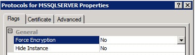
If your SQL server is forcing SQL SSL encryption, then you won’t get past the SSO installer as it will fail. You can validate your SQL server configuration by looking in the SQL Server Configuration Manager on your SQL server and reviewing the properties of the Protocols for MSSQLSERVER. As shown below, if Force Encryption is set to Yes you will need to change it to NO and restart the SQL services.

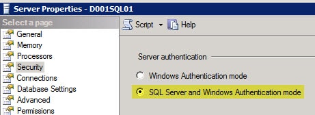
On another security note the SQL server MUST be configured to allow both Windows integrated authentication AND SQL authentication. SQL authentication is very weak, which makes the use of SSL for the database connection that much more imperative. Should the SQL server only allow Windows integrated authentication you will likely get the following error:

Error 29115.Cannot authenticate to DB.

Use SQL studio to login to your SQL server, open the server properties then use the less secure option of SQL Server and Windows Authentication mode. Restart the SQL services.


vCenter 5.1 Installation – VM Provisioning


1. Provision one or more VMs for the vCenter 5.1 install. In this blog series I’m assuming an all-in-one server to make things easier. You can certainly split up the services, which would be recommended in large environments.

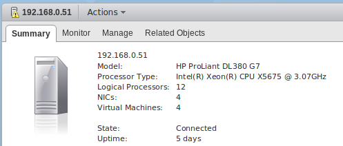
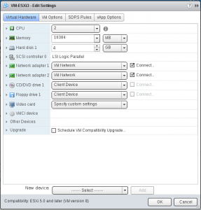
I provisioned a Windows Server VM with 2 HDs, and all of the latest Windows updates. 8GB of RAM for an all-in-one server is recommended, otherwise vCenter and SSO will run veryslowly. The 5.1 release has high memory utilization.

2. Create a domain-based service account which the vCenter services will use. Add that account to the local Administrator’s group on what will become the vCenter 5.1 server.

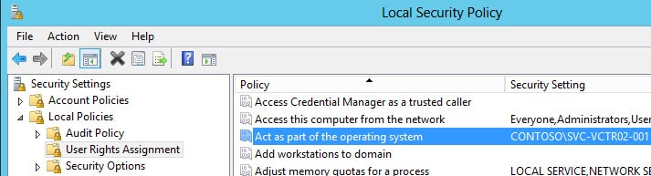
You need to ensure the service account also has the “Act as part of the operating system” user right on the vCenter server. If the Administrators group has the right then you are covered. If not, explicitly add the service account to the user right as shown below.


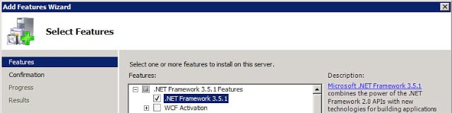
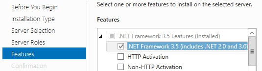
3. Open the Server Manager and add the .NET Framework 3.5 feature and wait for the install to complete.

Windows Server 2008 R2:


Windows Server 2012:


Do NOT install Java on the VM, as it can conflict with VMware version of Java.


Configure SQL Database


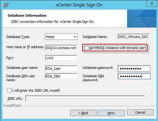
The vCenter Update 1 SSO install the wizard has been modified to support dynamic ports for SQL server instances.

Remember, VMware still does not officially support clustered SQL servers. They will provide best effort services if you run into issues, but it’s not a validated configuration.

The SSO service requires a database, as do other vCenter services. In this example we are using SQL Server 2012, but 2008 R2 SP2 is perfectly fine as well.

Prior to Update 1 SQL Server 2012 was NOT supported, so don’t try it unless you are on vSphere 5.1 Update 1.  There are some hard coded restrictions in the SSO service which limit your ability to use customized names for all of the fields. In particular the DB name must only include letters, numbers, underscore (_), the at symbol (@) and the hash (#). No periods and no spaces. As of the 5.1.0b release, hyphens are now allowed though.

As a reader has pointed out, you should be using SQL Server 2008 R2 SP1 and CU6 or later (Build 10.50.2811), which addresses a JDBC issue. You can read the MS KB here. I used SQL Server 2012 in my test environment, since that’s now supported as of vSphere 5.1 Update 1.

Be sure to set passwords on the SQL accounts that meet Windows GPO password complexity and minimum length requirements.

SQL DB Configuration Steps


1. VMware database script are included in the installation ISO. In my case I called the database “D001_VMware_SSO”. Run these scripts in SQL Server Management Studio, modified to your liking.

Note: that you CAN NOT change “RSA_DATA” or “RSA_INDEX” as the SSO service is hard coded to use them and the install WILL fail if they are not present.

Note: The VMware script has auto_shrink enabled, which DBAs tell me is a bad idea.


SSO Installation


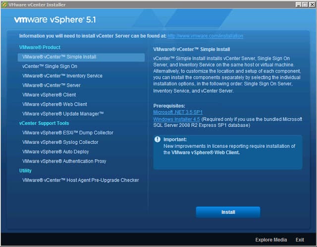
1. Login as the newly created vCenter service account and launch the vSphere installer from the ISO image and you are presented with the following screen.
vCenter 5.1 installation

At this point VMware gives you the option of a “Simple Install” or install each component separately.  We want to deliberately install each service and perform configuration steps along the way.

2. Click on vCenter Single Sign On, then click on Install. Select the appropriate language and wait for the wizard to open. After clicking through the licensing agreements and carefully reading all of the patents, you are presented with a screen with several options.

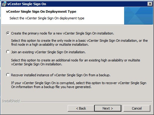
VMware gives you the option to install multiple instances of the SSO service for high availability. So on the screen below you have the option of creating a new primary node instance, or join an existing SSO instance. Since this is a new deployment, we want to create a primary node.
vCenter 5.1 installation

Even if you don’t want multiple SSO instances now, you may want them in the future. You don’t need to configure additional ones from the outset, so there’s no harm in leaving the door open for future expansion. Thus I selected the second option, as shown below. .

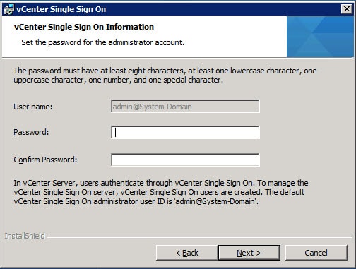
3. Next the installer will prompt you for the password to the default SSO Administrator account. Yes, this is a local account not tied to AD or the Windows host. After SSO is installed, you can configure it for one or more LDAP/AD server and other identity sources, so don’t fret too much about this application password but DO remember it.

The password must have at least eight characters, at least one lowercase character, one uppercase character, one number, and one special character. Maximum password length is 32 characters. Passwords longer than 32 characters will be truncated and cause authentication problems. The password also MUST meet local OS and AD domain length and complexity requirements. Password failures can cause the following SSO installation error:

Error 32010. Failed to create database users. There can be several reasons
for this failure. For more information, see the vmMSSQLCmd.log file in the
system temporary folder.


Note: Do NOT use the following characters, or trailing spaces:

^ (circumflex)
* (asterisk)
$ (dollar)
; (semicolon)
” (double quote)
‘ (single quote)
) (right parenthesis)
< (less than)
> (greater than)
& (ampersand)
| (pipe)
\ (backslash)

These may cause a “Error 29133.Administrator login error.” further on in the installation process. VMware has a KB article regarding these special characters here.

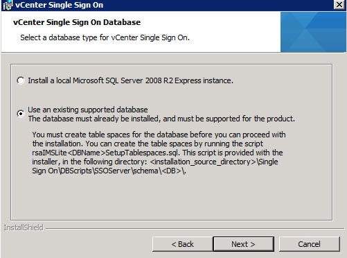
4. At this point you are presented with a dialog asking what kind of database you want to use. I would never use SQL Express in a lab or production environment, so select the second option.


5. Enter the database information in the window below, using the same details that you configured the SQL server with.


vSphere 5.1 Update SSO

Click on Next, and if everything is validated, no errors will appear.
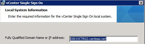
6. With your database details now properly configured, and maybe even using SSL to your SQL server, we can proceed with the SSO installer. If you were using a hardware load balancer, you would enter the FQDN of the VIP. Since I’m just installing one SSO instance, I’ll stick with the FQDN of the vCenter server.


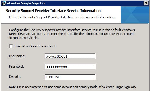
7. At this point input the vCenter service account details. Note that if you input the wrong password you will get an error “Could not find the specified user on provided domain.” which is not entirely correct. The user exists but you just fat fingered the password.


8. For the installation path I left the default, as the installer has had problems in the path with custom paths or “unusual” characters in the path.

9. On the next screen I left the HTTPS port the default, then sent the installer off on its merry way.


At this point the vCenter Single Sign On service should have successfully installed. Next up is creating all of the SSL certificates that the vCenter services require.


Storage Distributed Resource Scheduler (SDRS) algorithms and metrics

Storage Distributed Resource Scheduler (SDRS) provides initial placement of virtual machine disks and load balancing recommendations based on datastore latency and capacity.

Initial Placement

The initial placement of a virtual machine disk is computed based on space utilization and I/O load. When a datastore cluster is selected for one of the following scenarios, an initial placement is triggered:

  1. A virtual machine is created

  2. A virtual machine is cloned

  3. A virtual machine is migrated to a new datastore cluster

  4. A virtual machine is assigned a new disk


The intent of initial placement of a virtual machine disk is to reduce administrative complexity and ensure datastore performance. SDRS requires the administrator to select an appropriate datastore cluster. SDRS removes the administrator’s burden of manually calculating datastore  I/O and storage capacity. Based on the datastore cluster selected, SDRS will choose the most appropriate location to prevent cluster imbalance.

Profile Driven Storage

An administrator’s datastore cluster choice is further eased when SDRS is coupled with profile driven storage. The VM Storage Profiles feature found in vCenter, new to vSphere 5, eases the administrative burden of choosing an appropriate datastore cluster. When establishing a location for a new virtual machine, the administrator may reduce the list of available datastore cluster choices by selecting a pre-defined profile. A common example of storage tiering (profiles) is demonstrated below:

  1. Platinum – RAID 1, Enterprise Flash Drives

  2. Gold – RAID 10, 15K FC

  3. Silver – RAID 5, 10K FC

  4. Bronze – RAID 5, 7K SATA


Before going any further, I would like to point out that although you may easily select a datastore cluster based on a storage tier and SDRS may move the location of a virtual machine’s disk, it is still in the very best interest of your organization to keep record of static virtual machine settings. Documentation and change control is the key to establishing, maintaining, and supporting a healthy IT environment. /end rant

Datastore clusters

Datastore clusters were introduced in vSphere 5. A datastore cluster represents an aggregate of datastores. SDRS is automatically enabled upon the creation of a datastore cluster.

When designing a datastore cluster, you should ideally group disks with similar characteristics and take advantage of vSphere Storage API Storage Awareness (VASA) features if available for your storage arrays. Although it is technically feasible to have datastores with different storage characteristics as members of a datastore cluster, it is not in the best interest of your datastore cluster or virtual machine’s performance. Note that VMFS and NFS datastores cannot be part of the same datastore cluster.

Datastore cluster SDRS automation modes

A datastore cluster may be configured to operate in one of two modes:

  1. No Automation (Manual Mode) – Initial placement and migration recommendations are provided but it is the administrator’s responsibility to review and take action for each recommendation. This is the default mode after creating a datastore cluster.

  2. Fully Automated – Migration recommendations are executed automatically. Initial placement still requires administrator approval.


Virtual machine SDRS modes and operations

When the automation level is adjusted for individual virtual machines, the following options apply:


  1. Default (Manual) - Initial placement and migration recommendations are made but are not executed without administrator approval.

  2. Fully Automated – Initial placement and migrations occur automatically.

  3. Disabled – SDRS initial placement and migration recommendations are disabled. The resources in use by the virtual machine are still considered in the overall assessment of a datastore cluster. When SDRS is disabled, all settings relative to automation level, rules, thresholds and aggressiveness are saved until SDRS is reactivated.


Storage DRS Thresholds 


  1. Utilized Space – An adjustable value that is initially set at 80%. When this threshold is exceeded, SDRS will make recommendations.

  2. I/O Latency – Default value is 15 milliseconds. This value should be adjusted to reflect the type of disks used by the array that supports your datastores. When the 90th percentile I/O Latency is exceeded for the day, SDRS will make recommendations. When considering adjusting this setting, consult your storage vendor for best practices.


Advanced Options


  1. Evaluate I/O load every - This value will adjust the default interval that SDRS is invoked and may be adjusted from 60 minutes to 30 days. By default, SDRS load balancing algorithms are invoked at 8 hour intervals.

  2. No recommendations until utilization difference between source and destination is – This setting ensures that there is minimum amount of capacity difference between the source and target datastore. As an example, consider if the datastore cluster utilization threshold is set at 80% and datastore ‘A’ exceeded that value at 81%. It will consider migrating to datastore ‘B’ if the utilization capacity percentage difference is greater than the utilization difference setting. Further to this point, if the utilization difference value is set to 5 (the default), and datastore ‘B’ utilization is 77%, the difference is not great enough to trigger the migration. However, if datastore ‘C’ utilization capacity is currently at 76%, datastore ‘A’ would consider datastore ‘C’ as a viable migration target.

  3. I/O imbalance threshold - This setting is adjustable between conservative and aggressive. A conservative setting will only generate recommendations that would greatly impact the datastore cluster balance. An aggressive setting will generate recommendations for even the smallest benefit.


I/O Metric Inclusion

If this option is disabled, I/O metrics will not be considered for any SDRS recommendations. All calculations will be based on space utilization.


SDRS Rules

SDRS must consider anti-affinity rules in its migration recommendations. These rules are also in effect during initial placement. It will also make recommendations to correct any violated rules. You can setup anti-affinity rules to prevent two virtual disks from residing on the same datastore. SDRS Anti-affinity rules only apply to the cluster they are assigned. If a datastore is moved from the cluster, the rule does not apply.

SDRS supports the following rule types:

  1. Inter-VM Anti-Affinity Rules – This prevents virtual machines from residing on the same datastore.

  2. Intra-VM Anti-Affinity Rules – This prevents virtual disks from residing on the same datastore. For example, if a virtual machine has two disks, you may want them to run on different datastores.

  3. VMDK Affinity - By default, a virtual machine’s virtual disks are all contained within the same datastore. This may be overridden by adjusting the Keep VMDKs together option within the datastore cluster virtual machine settings dialog.


Load balancing assessments


The basis of SDRS recommendations is the consideration of both space utilization and I/O load analysis.

SDRS collects space utilization statistics for datastores within a datastore cluster at an interval of every two hours and compares this with the space utilization threshold. This assessment is repeated for all datastores within a datastore cluster prior to making a recommendation. When making placement recommendations based on space utilization, SDRS will recommend virtual machines that are powered off over those that are powered on.

SDRS analyzes historical statistics for the previous 24 hours of I/O load at 8 hour intervals. Although not recommended, you may adjust the interval that SDRS is invoked. The advanced setting Evaulate I/O load every 8 hours is the default value. Historical performance statistics along with an assessment of workload capabilities of each datastore are effectively baselined by an algorithm that represents the normalized load (a standard deviation) for each datastore. This value is ultimately compared to the I/O latency threshold defined for SDRS. If this threshold is exceeded by the normalized load, a cost benefit analysis is conducted prior to making any recommendations.

Any recommendations that are not acted upon expire at the next scheduled assessment.

SDRS issues migration recommendations for the follow events:

  1. Space utilization thresholds have been exceeded on a datastore

  2. I/O response time thresholds have been exceeded on a datastore

  3. A significant imbalance of capacity among datastores

  4. A significant imbalance of I/O among datastores


An SDRS assessment is triggered for the following events:

  1. When SDRS is manually executed

  2. During initial placement events

  3. When a datastore is added to a datastore cluster

  4. When a datastore is changed to maintenance mode

  5. When then SDRS configuration is updated

  6. When a threshold is exceeded

  7. At the defined interval (Default is 8 hours)


Storage I/O Control (SIOC) and SDRS

Both SIOC and SDRS have latency thresholds. The SDRS latency threshold should be set lower than the SIOC latency threshold. SIOC is for throttling I/O during times of contention whereas SDRS role is for avoiding contention. It would be better to rebalance the cluster if there are resources instead of throttling the workload.

It should be noted that the calculation for measuring latency is different for SIOC than SDRS. The SIOC latency threshold only considers device latency whereas SDRS considers device latency and queue latency.


Maintenance Mode

When a datastore is directed to be placed in maintenance mode, SDRS will only generate recommendations for registered virtual machines residing within the datastore targeted for maintenance mode. It is the administrators responsibility to determine if there are orphaned, unregistered, or other files residing on the datastore intended for maintenance mode and to manually take the appropriate action to preserve that data. Furthermore, if anti-affinity rules exist, it may prevent a datastore from entering maintenance mode. You may disabled Storage DRS rules for maintenance mode by setting theIgnore Affinity Rules for Maintenance option.
Scheduling SDRS

vCenter contains a feature for scheduling SDRS activity. For example, you may only want SDRS migrations to occur during off-peak hours and recommendations to occur during on-peak hours. Another example would be the need to disable migrations during backups. You can schedule the adjustment of many SDRS settings:


  1. Automation level

  2. Inclusion of I/O metrics for Storage DRS Recommendation

  3. Utilized space threshold

  4. I/O latency threshold

  5. I/O imbalance threshold


VMware vSphere Networking Best Practices

In a virtualized environment, there is a direct correlation between network throughput and CPU performance. To promote higher throughput, ensure that CPUs are not overworked. Monitor host and VM CPU usage regularly.

To guarantee noncompeting workloads, VMware recommends creating separate virtual switches for each physical adapter. Each adapter (or teams of adapters) can be dedicated to various traffic types (Virtual Machine, vMotion, IP Storage, etc). Implementing this design strategy will ease contention between VMs and the vmkernel. Note that this recommendation is more prevalent in environments where 1 GB adapters are in use predominantly. As datacenters shift to 10 GigE, more modern resource control methods such as Network I/O Control should be implemented.

Use Next Generation Physical Adapters

By using the latest and greatest physical network adapters in ESXi hosts, an administrator is able to take advantage of a variety of performance and offloading enhancements including:

TCP Checksum Offload - Checksum operations of network packets performed by the network adapter.

TCP Segmentation Offload (TSO) – Packet segmentation is performed by the network adapter. Promotes larger MTU sized frames. Reduces CPU strain on the VM.

Jumbo Frames - Support for ethernet frames with an MTU size up to 9,000 bytes, reducing the number of frames transmitted and received.

Jumbo Frames

Since there is a direct correlation between host and VM CPU performance and network bandwidth responsiveness. Decreasing CPU load will improve overall system performance and reduce latency. Enabling jumbo frames network wide can have that impact. By default, an ethernet MTU (maximum transmission unit) is 1,500 bytes.

The system is required to package and transmit each packet. As network speeds and application I/O increase, the impact of transmitting packets becomes more pronounced. Implementing jumbo frames enables an administrator to adjust the MTU size up to 9,000 bytes. Increasing the packet size unburdens the CPU by lessening packet transmission frequency. Note that the physical network must support jumbo frames end to end; network adapter, switch, router, etc.

After jumbo frames have been configured at the physical level, follow the steps below to extend the configuration to your virtual environment:

Enable Jumbo Frames on a vSphere Standard Switch (vSS)

  1. From the vSphere Client, connect to vCenter Server.
  2. Navigate to the Hosts and Clusters view (Ctrl+Shift+H).
  3. Select the appropriate ESXi host, click the Configuration tab.
  4. Ensure that the vSphere Standard Switch view is selected.
  5. Select Properties (next to the Standard Switch).
  6. On the Properties screen, select the Ports tab.
  7. Under Configuration, select the vSwitch, click Edit.
  8. Under Advanced Properties, adjust the MTU value (range is 1500 to 9000).
  9. Click OK, Close.

Enable Jumbo Frames on a vSphere Distributed Switch (vDS)

  1. Navigate to the Networking view (Ctrl+Shift+N).
  2. Right-click the appropriate vDS, select Edit Settings.
  3. On the vDS Settings screen, ensure that the Properties tab is selected.
  4. Select Advanced.
  5. Adjust the Maximum MTU value.
  6. Click OK.

To enable jumbo frames on the virtual machine, follow guest OS specific documentation.

VMXNET Virtual Network Adapters

Whenever possible, configure vmxnet as the virtual network adapter type for virtual machines. Using the latest vmxnet driver can improve performance in a few different ways.  The paravirtualized driver shares a ring buffer between the virtual machine and the vmkernel, supports transmission and interrupt coalescing and offloads TCP checksum calculations to the physical cards. These optimizations improve performance by reducing CPU cycles on the host and resident VMs. The vmxnet 3 adapter is the latest generation and was designed with performance in mind. In addition to the optimizations mentioned previously, it also provides multi-queue support and IPv6 offloads. Configuring the vmxnet 3 adapter requires at least hardware version 7 and a supported OS.

10 Gigabit Ethernet

To maximize the consolidation ratios of bandwidth-intensive VMs, use a 10 GigE infrastructure. Implementing 10 GigE increases the benefits of the performance enhancements listed above including TSO and jumbo frames. Using 10 GigE adapters reduces the the number of ESXi host slots and physical switch ports required to support intensive VM workloads.

One of the cool new features which 10 GigE enables is NetQueue. With NetQueue, multiple transmit and receive queues are used, so I/O load can be spread across multiple CPUs, increasing performance and reducing system latency.

Network I/O Control

Network I/O Control (NIOC) was released with vSphere 4.1. NIOC allows an administrator to enable network resource pools to control network utilization. NIOC extends the configurability of shares and limits to network bandwidth. This flexibility can be extremely valuable in 10 GigE environments. Note that NIOC only applies to outgoing (egress) traffic and is limited to distributed switches.

When NIOC is enabled on a vSphere 5.0 distributed switch, seven (7) predefined network resource pools are created for the following traffic types; vMotion, Virtual Machine, NFS, Management, iSCSI, Fault Tolerance (FT) and Host Based Replication traffic. An administrator can manipulate settings in the system defined network resource pools or create user defined network resource pools for even further flexibility.

SplitRx Mode

SplitRx mode is an ESXi feature new to version 5 which enables multiple CPUs to handle network packets coming from the same queue. SplitRx Mode can be beneficial for a couple different workload scenarios. For example, if multiple VMs on the same host receive multicast traffic from the same source. SplitRx mode is only supported on VMs configured with the vmxnet 3 virtual adapter. The feature can be manipulated by editing the VM’s configuration (.vmx) file. To enable SplitRx mode, set the value of ethernetX.emuRxMode to 1.

References

  1. Determine use cases for and configure VMware DirectPath I/O in vSphere 5
  2. Performance Best Practices for VMware vSphere 5.0
  3. Mastering VMware vSphere 5.0 (Chapter 11) – Lowe

New free tool - HP Virtualization Performance Viewer

This new free tool caught my eye when it was mentioned on an internal email chain, it’s called the HP Virtualization Performance Viewer (vPV). It’s a lightweight tool that provides real-time performance analysis reporting for to help diagnose and triage performance problems. It’s a Linux based utility and can be installed natively on any VM/PC running Linux or it can be deployed as a virtual appliance. It supports both VMware vSphere & Microsoft Hyper-V environments and has the following features:

  • Quick time to value
  • Intuitive at-a-glance dashboards
  • Triage virtualization performance issues in real-time
  • Foresee capacity issues and identify under / over utilized systems
  • Operational and status report for performance, up-time and distribution analysis

The free version of vPV has some limitations, to achieve the full functionality you need to upgrade to the Enterprise version but the free version should be good enough for smaller environments.

hpv2

It’s simple and easy to download the tool, just head over to the HP website, enter some basic information and you get the download page where you can choose the files that you want to download based on your install preference.

hpv11Downloading the OVA file to install the virtual appliance is the easiest way to go, once you download it, you simply deploy it using the Deploy OVF Template option in the vSphere Client and it will install as a new VM. Once deployed and powered on you can log in to the VM’s OS using the username root and password vperf*viewer if you need to manually configure an IP address. Otherwise you can connect to the VM and start using vPV using the URL: http://<servername>:8081/PV OR https://<servername>:8444/PV which will bring up the user interface so you can get started. I haven’t tried it out yet as it’s still downloading but here’s some screenshots from the vPV webpage:

hpv3hpv4

Tips for monitoring applications in a Virtual Environment

The focus on applications often gets lost in the shuffle when implementing virtualization which is unfortunate because if you look at any server environment its sole purpose is really to serve applications. No matter what hardware, hypervisor or operating system is used, ultimately it all comes down to being able to run applications that serve a specific function for the users in a server environment. When you think about it, without applications we wouldn’t even have a need for computing hardware, so it’s important to remember, it’s really all about the applications.

So with that I wanted to provide 5 tips for monitoring applications in a virtual environment that will help you ensure that your applications run smoothly once they are virtualized.

Tip 1 – Monitor all the layers

The computing stack consists of several different components all layered on top of each other. At the bottom is the physical hardware or bare metal as it is often referred to. On top of that you traditionally had the operating system like Microsoft Windows or Linux, but with virtualization you have a new layer that sits between the hardware and the operating system. The virtualization layer controls all access to physical hardware and the operating system layer is contained within virtual machines. Inside those virtual machines is the application layer where you install applications within the operating system. Finally you have the user layer that accesses the applications running on the virtual machines. Within each layer you have specific resource areas that need to be monitored both within and across layers. For example storage resources which are a typical bottleneck in virtual environments need storage management across layers so you get different perspectives from multiple viewpoints.

To have truly effective monitoring you need to monitor all the layers so you can get a perspective from each layer and also see the big picture interaction between layers. If you don’t monitor all the layers you are going to miss important events that are relevant at a particular layer. For example if you focus only on monitoring at the guest OS layer, how do you know your applications or performing as they should or that your hypervisor does not have a bottleneck. So don’t miss anything when you monitor your virtual environment, you should monitor the application stack from end to end all the way from the infrastructure to the applications and the users that rely on them.

Tip 2 – Pay attention to the user experience

So you monitor your applications for problems but that won’t necessarily tell you how well it’s performing from a user perspective. If you’re just looking at the application and you see it has plenty of memory and CPU resources and there are no error messages you might get a false sense of confidence that it is running OK. If you dig deeper you may uncover hidden problems, this is especially true with virtualized applications that run on shared infrastructure and multi-tier applications that span servers that rely on other servers to properly function.

The user experience is what the user experiences when using the application and is the best measure of how an application is performing. If there is a bottleneck somewhere between shared resources or in one tier of an application it’s going to negatively impact the user experience which is based on everything working smoothly. So it’s important to have a monitoring tool that can simulate a user accessing an application so you can monitor from that perspective. If you detect that the user experience has degraded many tools will help you pinpoint where the bottleneck or problem is occurring.

Tip 3 – Understand application and virtualization dependencies

There are many dependencies that can occur with applications and in virtual environments. With applications you may have a multi-tier application that depends on other services running on other VMs such as a web tier, app tier and database tier. Multi-tier applications are typically all or nothing, if any one tier is unavailable or has a problem the application fails. Clustering can be leveraged within applications to provide higher availability but you need to take special precautions to ensure a failure doesn’t impact the entire clustered application all at once. This may also extend beyond applications into other areas, for example if Active Directory or DNS is unavailable it may also affect your applications. In addition there are also many dependencies inside a virtual environment. One big one is shared storage, VMs can survive a host failure with HA features that bring them up on another host, but if your primary shared storage fails it can take down the whole environment.

The bottom line is that you have to know your dependencies ahead of time, you can’t afford to find them out when problems happen. You should clearly document what your applications need to be able to function and ensure you take that into account in our design considerations for your virtual environment.  Something as simple as DNS being unavailable can take down a whole datacenter as everything relies on it. You also need to go beyond understanding your dependencies and configure your virtual environment and virtualization management around them. Doing things like setting affinity settings so when VMs are moved around they are either kept together or spread across hosts will help minimize application downtime and balance performance.

Tip 4 – Leverage VMware HA OS & application heartbeat monitoring

One of the little known functions of VMware’s High Availability (HA) feature is the ability to monitor both operating systems and applications to ensure that they are responding. HA was originally designed to detect host failures in a cluster and automatically restart VMs on failed hosts on other hosts in the cluster. It was further enhanced to detect VM failures such as a Windows blue screen by monitoring a heartbeat inside the VM guest OS through the VMware Tools utility. This feature is known as Virtual Machine (VM) Monitoring and will automatically restart a VM if it detects the loss of the heartbeat. To help avoid false positives it was further enhanced to detect I/O occurring by the VM to ensure that it was truly down before restarting it.

VMware HA Application Monitoring was introduced as a further enhancement to HA in vSphere 5 that took HA another level deeper, to the application. Again leveraging VMware Tools and using a special API that VMware developed for this you can now monitor the heartbeat of individual applications. VMware’s API allows application developers for any type of application, even custom ones developed in-house to hook in to VMware HA Application Monitoring to provide an extra level of protection by automatically restarting a VM if an application fails. Both features are disabled by default and need to be enabled to function, in addition with application monitoring you need to be running an application that supports it.

Tip 5 – Use the right tool for the job

You really need a comprehensive monitoring package that will monitor all aspects and layers of your virtual environment. Many tools today focus on specific areas such as the physical hardware or guest OS or the hypervisor. What you need are monitoring tools that can cover all your bases and also focus on your applications which are really the most critical part of your whole environment. Because of the interactions and dependencies with applications and virtual environments you also need tools that can understand them and properly monitor them so you can troubleshoot them more easily and spot bottlenecks that may choke your applications. Having a tool that can also simulate the user experience is especially important in a virtualized environment that has so many moving parts so you can monitor the application from end-to-end.

SolarWinds can provide you with the tools you need to monitor every part of your virtual environment including the applications. SolarWinds Virtualization Manager coupled with Server & Application Monitor can help ensure that you do not miss anything and that you have all the computing layers covered. SolarWinds Virtualization Manager delivers integrated VMware and Microsoft Hyper-V capacity planning, performance monitoring, VM sprawl control, configuration management, and chargeback automation to provide complete monitoring of your hypervisor.

SolarWinds Server & Application Monitor delivers agentless application and server monitoring software that provides monitoring, alerting, reporting, and server management. It only takes minutes to create monitors for custom applications and to deploy new application monitors with Server & Application Monitor’s built-in support for more than 150 applications. Server management capabilities allow you to natively start and stop services, reboot servers, and kill rogue processes. It also enables you to measure application performance from an end user’s perspective so you can monitor the user experience.

With SolarWinds Virtualization Manager and SolarWinds Server & Application Monitor you have complete coverage of your entire virtual environment from the bare metal all the way to the end user.

vMotion fails with the error: A general system error occurred: Failed waiting for data. Error bad0007. Bad parameter

Symptoms:


  • Migrating virtual machines fails when one of the following occurs:


    • You enable Migrate.MemChksum (value is set to 1) on both source and destination ESX hosts.


    • The virtual machine has a memory size of more than 4GB


  • The migration times out and the following error appears in the vmware.log file: MigrateStatusFailure: Failed waiting for data. Error bad0007. Bad parameter>and the VMware Infrastructure Client reports the following error:

    A general system error occurred: Failed waiting for data. Error bad0007. Bad parameter.


  • vMotion fails at 10%


Resolution:
Configure the value of the following variables in the source and the destination ESX hosts. The variables are available at Configuration > Advanced Settings > Migrate 


  • Migrate.PageInTimeoutResetOnProgress: Set the value to 1.

  • Migrate.PageInProgress: Set the value to 30, if you get an error after configuring theMigrate.PageInTimeoutResetOnProgress variable.

  • Toggle the Migrate.enabled setting from 1 to 0, click OK, then flip the value back to 1, click OK.